Operation, Using the capacity chart – SkyTrak 3606 Operation Manual User Manual
Page 70
68
3606 Rev 11/99
Operation
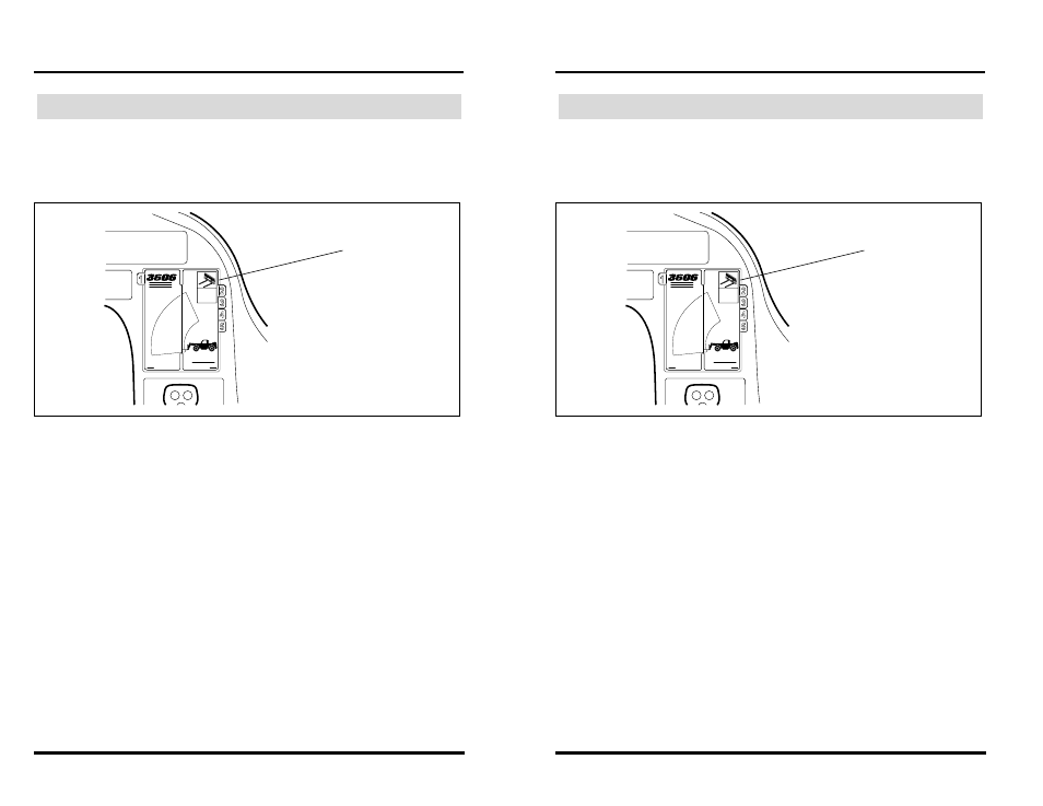
The individual capacity charts are located inside a booklet on the right side
of the operator’s compartment. Capacity charts are provided to assist the
operator in determining how far in front, how high and at what angle a
specific load can be safely handled with this vehicle.
Figure 44
The vehicle is equipped with two indicators that will assist the operator in
determining how to accurately use the capacity chart. These indicators are:
• boom extend stripes (Figure 45)
• boom angle indicator (Figure 46)
As the boom is extended, boom extend stripes become visible on the left
side of the intermediate boom. These stripes indicate the point of boom
extension and correspond to the capacity chart. For example, when the
boom extend “B” stripe first appears, the boom is at the point of boom
extension corresponding to an arc of line “B” on the capacity chart.
Using the Capacity Chart
OS1680
Capacity
Chart
Booklet
68
3606 Rev 11/99
Operation
The individual capacity charts are located inside a booklet on the right side
of the operator’s compartment. Capacity charts are provided to assist the
operator in determining how far in front, how high and at what angle a
specific load can be safely handled with this vehicle.
Figure 44
The vehicle is equipped with two indicators that will assist the operator in
determining how to accurately use the capacity chart. These indicators are:
• boom extend stripes (Figure 45)
• boom angle indicator (Figure 46)
As the boom is extended, boom extend stripes become visible on the left
side of the intermediate boom. These stripes indicate the point of boom
extension and correspond to the capacity chart. For example, when the
boom extend “B” stripe first appears, the boom is at the point of boom
extension corresponding to an arc of line “B” on the capacity chart.
Using the Capacity Chart
OS1680
Capacity
Chart
Booklet