Mixed stp and rstp networks, Spanning tree and vlans, Sales vlan production vlan – Allied Telesis AT-S25 User Manual
Page 100: Vlan sales vlan, Production, L /a, L /a d/c d/c l /a d/c
Section II: Local and Telnet Mangement
100
Mixed STP and
RSTP Networks
RSTP IEEE 802.1w is fully compliant with STP IEEE 802.1d. Your network
can consist of bridges running both protocols. STP and RSTP in the same
network should be able to operate together to create a single spanning
tree domain.
There is no reason not to activate RSTP on an AT-8316F or an AT-8324
Switch even when all other switches are running STP. The AT-8316F or
AT-8324 Switch can combine its RSTP with the STP of the other switches.
An AT-8316F or AT-8324 Switch will monitor the traffic on each port for
BPDU packets. Ports that receive RSTP BPDU packets will operate in RSTP
while ports receiving STP BPDU packets will operate in STP.
Spanning Tree
and VLANs
The spanning tree implementation on an AT-8316F or an AT-8324
Switch is a single-instance spanning tree. The switch supports just one
spanning tree. You could not define multiple spanning trees.
The single spanning tree encompasses all ports on the switch. If the
ports are divided into different VLANs, the spanning tree crosses the
VLAN boundaries. This point can pose a problem in networks containing
many VLANs that span different switches and are connected with
untagged ports. What can happen is that STP will block a data link
because it detects a data loop. This can cause fragmentation of your
VLANs.
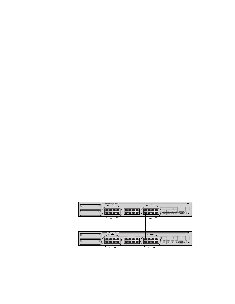
This issue is illustrated in Figure 34. Two VLANs, Sales and Production,
span two AT-8324 Switches. Two links consisting of untagged ports
interconnect the separate parts of each VLAN. If STP is activated on the
switch, one of the links would be disabled. This problem can be avoided
by not activating spanning tree or by connecting VLANs using tagged
instead of untagged ports. (For information on tagged and untagged
ports, refer to Chapter 10, Virtual LANs on page 117.
Figure 34 VLAN Fragmentation
STATUS
RESET
FAULT
MASTER
RPS
PWR
10BASE-T / 100BASE-TX
FAST ETHERNET SWITCH
1
2
3
4
5
6
7
8
9
10
11
12
13
14
15
16
17
18
19
20
21
22
23
24
10BASE-T / 100BASE-TX
1X
3X
5X
7X
2X
4X
6X
8X
9X
11X
13X
15X
10X
12X
14X
16X
17X
19X
21X
23X
18X
20X
22X
24X
A
B
RS-232
TERMINAL PORT
100M LINK / ACTIVITY
10M LINK / ACTIVITY
HALF DUP/ COL
FULL DUP
PORT ACTIVITY
L /A
L /A
D/C
D/C
L /A
D/C
Sales
VLAN
Production
VLAN
Production
VLAN
Sales
VLAN
STATUS
RESET
FAULT
MASTER
RPS
PWR
10BASE-T / 100BASE-TX
FAST ETHERNET SWITCH
1
2
3
4
5
6
7
8
9
10
11
12
13
14
15
16
17
18
19
20
21
22
23
24
10BASE-T / 100BASE-TX
1X
3X
5X
7X
2X
4X
6X
8X
9X
11X
13X
15X
10X
12X
14X
16X
17X
19X
21X
23X
18X
20X
22X
24X
A
B
RS-232
TERMINAL PORT
100M LINK / ACTIVITY
10M LINK / ACTIVITY
HALF DUP/ COL
FULL DUP
PORT ACTIVITY
L /A
L /A
D/C
D/C
L /A
D/C