Cascade – Watlow Series F4S/D User Manual
Page 75
Wa t l o w S e r i e s F 4 S / D
F e a t u r e s
■
6 . 1 1
Cascade
Cascade control is a control strategy in which one
control loop provides the set point for another loop.
It allows the process or part temperature to be
reached quickly while minimizing overshoot. Cas-
cade is used to optimize the performance of thermal
systems with long lag times.
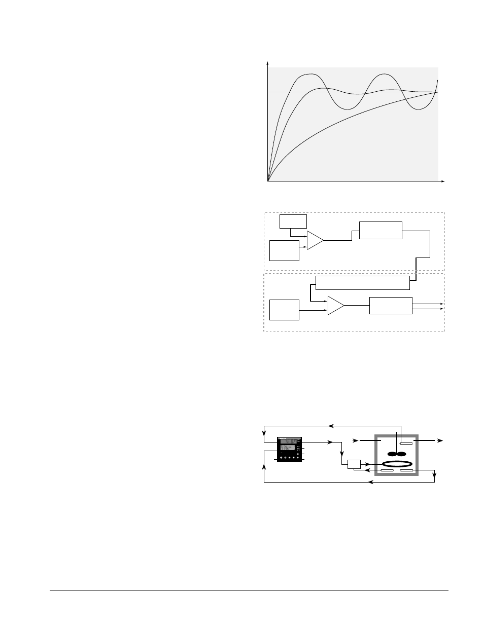
This graph illustrates a thermal system with a long
lag time. Curve A represents a single-loop control
system with PID parameters that allow a maximum
heat-up rate. Too much energy is introduced and the
set point is overshot. In most systems with long lag
time, the process value may never settle out to an
acceptable error. Curve C represents a single-control
system tuned to minimize overshoot. This results in
unacceptable heat-up rates, taking hours to reach
the final value. Curve B shows a cascade system
that limits the energy introduced into the system,
allowing an optimal heat-up rate with minimal over-
shoot.
Cascade control uses two control loops (outer and in-
ner) to control the process. The outer loop (analog
input 3) monitors the process or part temperature,
which is then compared to the set point. The result
of the comparison, the error signal, is acted on by
the settings in a Cascade Outer Loop PID set (1 to
5), which then generates a power level for the outer
loop. The set point for the inner loop is determined
by the outer-loop power level and the Cascade Low
Range/Deviation and the Cascade High Range/Devi-
ation settings for analog input 3.
The inner loop (analog input 1) monitors the energy
source (heating and cooling), which is compared to
the inner loop set point generated by the outer loop.
The result of the comparison, the error signal, is act-
ed on by the settings in a Cascade Inner Loop PID
set (1 to 5), which generates an output power level
between -100% to +100%. If the power level is posi-
tive the heat will be on; if the power level is nega-
tive the cool will come on.
In Series F4 controllers, cascade control is available
on channel 1. Analog input 3 is used to measure the
outer-loop process while analog input 1, the inner
loop, is used to measure the energy source. Power
from the energy sources are supplied by outputs 1A
and 1B.
To set up and tune a system for cascade control, see
the Operations Chapter.
Location in software: Setup Page and Operations
Page.
Figure 6.11a — Control Lag Times.
✔ NOTE
:
Cascade Low Range and Cascade High Range Set
Points for Input 1 (as shown above) are setup under Analog In-
put 3. Refer to Setup Chapter.
Figure 6.11b — Cascade Control.
Figure 6.11 — Cascade Example
Error Signal
(Heat)
0 to 100%
(Cool)
0 to -100%
Percent Power
0% to 100%
Set Point
(Process Part)
Input 3
Outer Loop
(Process Part)
Input 1
Inner Loop
(Energy Source)
Control Outer Loop
PID Set 1-5
ES/PB x 100 = % Out
Cascade Inner Loop
PID Set 1-5
ES/PB x 100 = % Out
0% = Cascade Low Range/Deviation
100% = Cascade High Range/Deviation
Error Signal
+
-
+
-
Outer Loop
Inner Loop
Time
Temperature
Curve A (PID)
Set
Point
Curve B (Cascade)
Curve C (Single-control)
input
1
input
3
output 1
limit
limit sensor
oil in
heater
oil out
inner-loop
thermocouple
Lube O il Ta nk
outer-loop
thermocouple
F
4
1
2
1B
1B
1A
1A
A
M
/