Communications wiring, Eia/tia-232 connections, Figure 12.10a – Watlow Series F4S/D User Manual
Page 132: Figure 12.10b, Figure 12.10c
1 2 . 1 0
■
W i r i n g
Wa t l o w S e r i e s F 4 S / D
Communications Wiring
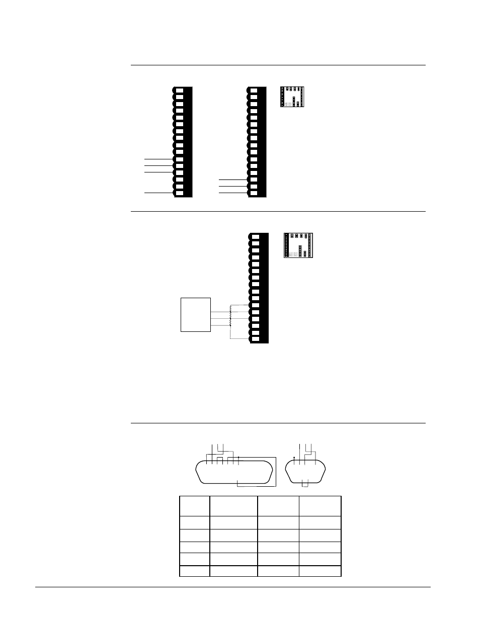
Figure 12.10a —
EIA/TIA 485 and EIA/TIA 232 Communications
Figure 12.10b —
Termination for EIA-232 to EIA-485 Converter
If the system does not work properly, it may need termination resistors at each
end of the network. A typical installation would require a 120-ohm resistor
across the transmit/receive terminals (12 and 13) of the last controller in the
network and the converter box or serial card. Pull-up and pull-down 1k resistors
may be needed on the first unit to maintain the correct voltage during the idle
state.
Figure 12.10c —
EIA/TIA-232 Connections
B
A
GND
+5V
T+/R+
T-/R-
1K
Ω
120
Ω
1K
Ω
Converter box
termination
with pull-up
and pull-down
resistors.
1 2 3 4 5 6 7 8 9 10 11 12 13 14 1 2 3 4 5 6 7 8 9 10 11 12 13 14
15 16
Com
1 2 3 4 5 6 7 8 9 10 11 12 13 14 1 2 3 4 5 6 7 8 9 10 11 12 13 14
15 1615 16
17 18 19 20 21 22 23 24 25 26 27 28 29 30 31 3217 18 19 20 21 22 23 24 25 26 27 28 29 30 31 32
59
6
0
61 62
59 60 61 62
48
4
9
50
48 49 50
45
4
6 47
45 46 47
51
5
2 53
54 55
56 57
58
51 52 53 54 55 56 57 58
33 34 3533 34 35
36 37 3836 37 38
39 40 4139 40 41
42 43 4442 43 44
1 2 3 4 5 6 7 8 9 10 11 12 13 14 1 2 3 4 5 6 7 8 9 10 11 12 13 14
15 1615 16
17 18 19 20 21 22 23 24 25 26 27 28 29 30 31 3217 18 19 20 21 22 23 24 25 26 27 28 29 30 31 32
5
9 60 61 62
59 60 61 62
48 49 5048 49 50
45 46 4745 46 47
51
52 53 54 55 56
57 58
51 52 53 54 55 56 57 58
33 34 3533 34 35
36 37 3836 37 38
39 40 4139 40 41
42 43 4442 43 44
11
12
1 2 3 4 5 6 7 8 9 10 11 12 13 14 1 2 3 4 5 6 7 8 9 10 11 12 13 14
15 16
T+/R+
5V+ termi-
nation bias
13
T-/R-
14
15
1 2 3 4 5 6 7 8 9 10 11 12 13 14 1 2 3 4 5 6 7 8 9 10 11 12 13 14
15 16
Receive
Transmit
16
COM.
EIA/TIA 485
EIA/TIA 232
16
COM.
ç
WARNING:
To avoid damage to
property and equipment,
and/or injury of loss of
life, use National Electric
Code (NEC) standard
wiring practices to install
and operate the Series
F4. Failure to do so could
result in such damage,
and/or injury or death.
¥ ¥ ¥ ¥ ¥ ¥ ¥ ¥ ¥ ¥ ¥ ¥ ¥
1 2 3 4 5 6 7 8 9 10 11 12 13
14 15 16 17 18 19 20 21 22 23 24 25
¥ ¥ ¥ ¥ ¥ ¥ ¥ ¥ ¥ ¥ ¥ ¥
¥ ¥ ¥ ¥ ¥
1 2 3 4 5
6 7 8 9
¥ ¥ ¥ ¥
14 16 15
14 16 15
Wire
F4
DB 9
DB25
Color
232
Connector
Connector
White
TX Pin 14
RX Pin 2
RX Pin 3
Red
RX Pin 15
TX Pin 3
TX Pin 2
Black
GND Pin 16
Gnd Pin 5
GND Pin 7
Green
GND Pin 24
N/U Pin 9
N/U Pin 22
Shield
N/C
Gnd Pin 5
Gnd Pin 7