Panel dimensions, Installing the series f4 controller, Panel cutout – Watlow Series F4S/D User Manual
Page 120
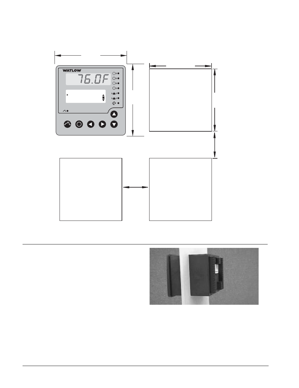
Panel Dimensions
Figure 11.2a — Multiple Panel Cutout Dimensions.
Installing the Series F4 Controller
Installing and mounting requires access to the back
of the panel.
Tools required: one #2 Phillips screwdriver.
1. Make the panel cutout using the mounting
template dimensions in this chapter.
2. Insert the controller into the panel cutout.
Check that the rubber gasket lies in its slot at
the back of the bezel. Slide the retention collar
over the case, with open holes facing the back of
the case.
Figure 11.2b — Gasket Seated on the Bezel.
3. Align the mounting bracket with the screws tips
pointed toward the panel. Squeezing the bowed
sides of the bracket, push it gently but firmly
over the case until the hooks snap into the slots
at the front of the case.
Panel Cutout
Panel
Thickness
0.375 in. maximum
(9.5 mm)
3.62 to 3.651 in.
(92 to 93 mm)
0.675 in.
(17.6 mm)
minimum
0.625 in.
(16 mm)
minimum
3.930 in.
(99.8 mm)
3.930 in.
(99.8 mm)
F
4
1
2
1B
1B
2A
2A
2B
2B
1A
1A
Main Page___________
Go to Profiles
Go to Setup
Go to Factory
i
3.62 to 3.65 in.
(92 to 93 mm)
1 1 . 2
■
I n s t a l l a t i o n
Wa t l o w S e r i e s F 4 S / D