Wiring example, Figure 12.12 — system wiring example – Watlow Series F4S/D User Manual
Page 134
1 2 . 1 2
■
W i r i n g
Wa t l o w S e r i e s F 4 S / D
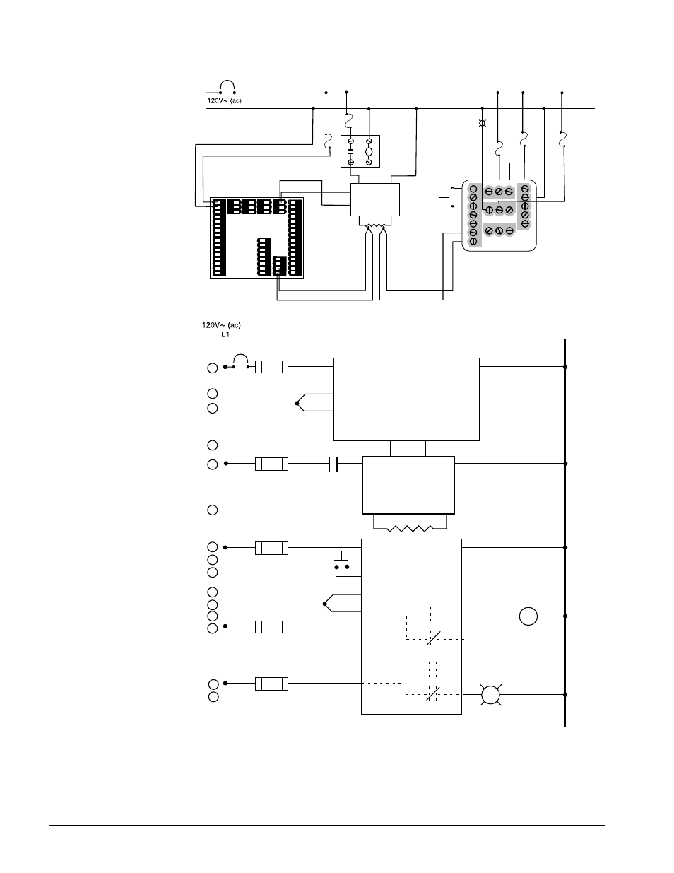
Wiring Example
Figure 12.12 — System Wiring Example.
1
L2
2
61
62
4
5
1
2
1
2
(+)
(-)
3
12
20
13
14
15
16
2
1CR
17
high-temperature light
1
2
3
4
8
9
10
11
12
R
18
1
8
(+)
(-)
1 CR-1
9
2
44
42
6
7
1
2
5
6
7
Series F4
F4_H - CA_ _ - 01RG
Temperature Controller
Series 97
97A1-DDAA-00RR
Limit Controller
13
14
15
14
15
18
6
9
8
1
3
7
(+)
(-)
Heater
DIN-A-MITE
DA10-24C0-0000
2
1
3
4
10
11
1
17
19
5
6
Series F4
F4 _ H - CA _ _ - O1RG
rear view
1
2
61 (+)
44 (dc+)
42 (dc-)
L1
L2
fuse
97A1-DDAA-00RR
Limit Controller
process sensor
limit sensor
optional
normally open
momentary switch
high-limit
mechanical
contactor
7 (+)
6 (-)
high-
temperature
light
coil
62 (-)
10
8
1
2
3
4
5
6
7
13 14 15
11
12
16 17 18
19 20 21
9
1
3
16
14
15
17
9
1 2 3 4 5 6 7 8 9 10 11 12 13 14 1 2 3 4 5 6 7 8 9 10 11 12 13 14
15 1615 16
17 18 19 20 21 22 23 24 25 26 27 28 29 30 31 3217 18 19 20 21 22 23 24 25 26 27 28 29 30 31 32
59 60 61 6259 60 61 62
51 52 53 54 55 56 57 58 51 52 53 54 55 56 57 58
33 34 3533 34 35
36 37 3836 37 38
39 40 4139 40 41
42 43 4442 43 44
Heater
DIN-A-MITE
DA10-24C0-0000
2
1
3
4
5
(-)
(+)
6
8
ç
WARNING:
To avoid damage to
property and equipment,
and/or injury of loss of
life, use National Electric
Code (NEC) standard
wiring practices to install
and operate the Series
F4. Failure to do so could
result in such damage,
and/or injury or death.
ç
WARNING:
Install high- or low-
temperature-limit control
protection in systems
where an over-
temperature fault
condition could present a
fire hazard or other
hazard. Failure to install
temperature limit control
protection where a
potential hazard exists
could result in damage to
equipment, property and
injury to personnel.