Input 2 & 3, Inputs x (2 and 3), Thermocouple – Watlow Series F4S/D User Manual
Page 126: Rtd (2-wire) 100 ω platinum, Rtd (3-wire) 100 ω platinum, Figure 12.4a, Figure 12.4b, Figure 12.4c
1 2 . 4
■
W i r i n g
Wa t l o w S e r i e s F 4 S / D
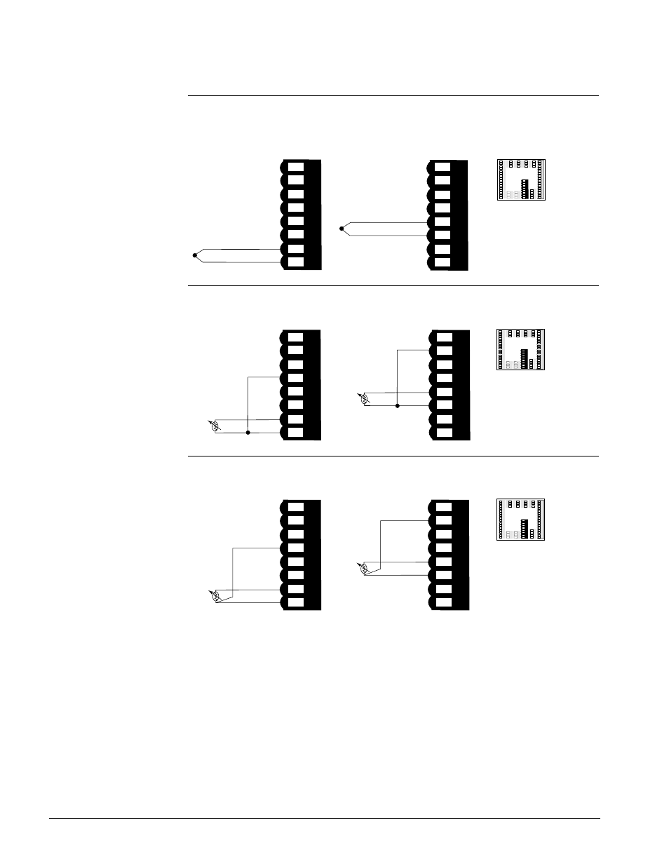
Inputs x (2 and 3)
Figure 12.4a —
Thermocouple
F4S _ - _ _ _ 6 - _ _ _ _ or F4D _ - _ _ _ _ - _ _ _ _
Impedance: 20M
Ω
Figure 12.4b —
RTD (2-wire) 100
Ω
Platinum
F4S _ - _ _ _ 6 - _ _ _ _ or F4D _ - _ _ _ _ - _ _ _ _
Figure 12.4c —
RTD (3-wire) 100
Ω
Platinum
F4S _ - _ _ _ 6 - _ _ _ _ or F4D _ - _ _ _ _ - _ _ _ _
51 52 53 54 55 56 57 58
54
57
58
S1
S3
S2
51 52 53 54 55 56 57 58
52
55
56
S1
S3
S2
Input 2
Input 3
1 2 3 4 5 6 7 8 9 10 11 12 13 1
4
1 2 3 4 5 6 7 8 9 10 11 12 13 14
15 1615 16
17
1
8 19 2
0 2
1 22 23 24 25 26 27 28 29 30 31 32
17 18 19 20 21 22 23 24 25 26 27 28 29 30 31 32
59 60 61 6259 60 61 62
48 49 5048 49 50
45 46 4745 46 47
51 52 53 54 55 56 57 58 51 52 53 54 55 56 57 58
33 34 3533 34 35
3
6 37 38
36 37 38
39 40 4139 40 41
42 43 4442 43 44
51 52 53 54 55 56 57 58
54
57
58
S1
S3
jumper 54 to 58
51 52 53 54 55 56 57 58
52
55
56
S1
S3
jumper 52 to 56
Input 2
Input 3
1 2 3 4 5 6 7 8 9 10 11 12 13 14 1 2 3 4 5 6 7 8 9 10 11 12 13 14
15 1615 16
17 18 19 20 21 22 2
3 24 25 26 27 28 29 30 31 32
17 18 19 20 21 22 23 24 25 26 27 28 29 30 31 32
59 60 61 6259 60 61 62
48 49 5048 49 50
45 46 4745 46 47
51 52 53 54 5
5 56 57
58
51 52 53 54 55 56 57 58
33 34 3533 34 35
36 37 3
8
36 37 38
39 40 4139 40 41
42 43 4442 43 44
+57
-58
51 52 53 54 55 56 57 58
+55
-56
51 52 53 54 55 56 57 58
Input 2
Input 3
1 2 3 4 5 6 7 8 9 10 11 12 13 1
4
1 2 3 4 5 6 7 8 9 10 11 12 13 14
15 1615 16
17 18 19 20 21 22 23 24 2
5 26 27 28 29 30 31 32
17 18 19 20 21 22 23 24 25 26 27 28 29 30 31 32
59 60 6
1 62
59 60 61 62
48
49 50
48 49 50
45 46 4745 46 47
51
52 53 54 55 56 57 58
51 52 53 54 55 56 57 58
33 34 3533 34 35
3
6 37 38
36 37 38
39 40 4139 40 41
42 43 4442 43 44
ç
WARNING:
To avoid damage to
property and equipment,
and/or injury of loss of
life, use National Electric
Code (NEC) standard
wiring practices to install
and operate the Series
F4. Failure to do so could
result in such damage,
and/or injury or death.
ç
CAUTION:
Maintain isolation
between analog inputs 2
and 3, and between
analog input 1 and digital
inputs 1 to 4 to prevent a
ground loop. A ground
loop may cause incorrect
readings. Failure to
follow this guideline
could result in damage to
equipment and product.