Removing the series f4 controller – Watlow Series F4S/D User Manual
Page 121
4. If the installation does not require a NEMA 4X
seal, tighten the four screws with the Phillips
screwdriver just enough to eliminate the
spacing between the rubber gasket and the
mounting panel.
For a NEMA 4X seal, tighten the four screws
until the gap between the bezel and panel
surface is .020 in. maximum. (See figure 11.1b).
Make sure that you cannot move the controller
back and forth in the cutout. If you can, you do
not have a proper seal. Do not over tighten.
Over tightening could damage the the
mounting bracket.
Removing the Series F4 Controller
The controller can be removed most easily by
disengaging the mounting bracket hooks and
pushing the controller forward through the panel.
Be ready to support it as it slides forward through
the panel.
Tools required: one #2 Phillips screwdriver, one flat-
head screwdriver and some means of supporting
the controller as it slides out the front of the panel.
1. Remove all the wiring connectors from the back
of the controller. Using the Phillips screwdriver,
unscrew the four screws on the mounting
bracket (two on top, two on bottom) until the
tips are completely retracted into the shafts.
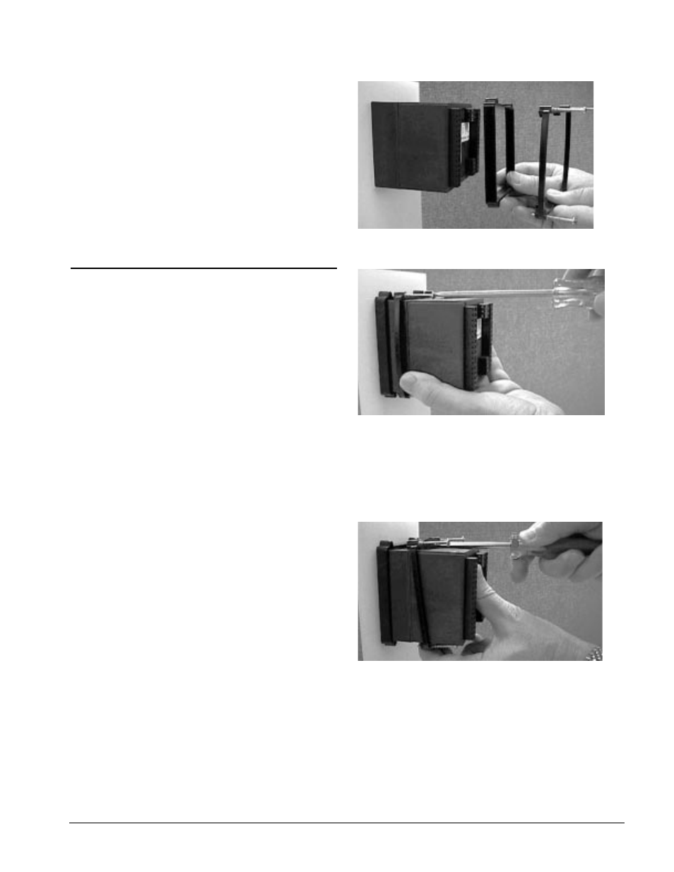
2. Slide the tip of a flat screwdriver between the
case and the center top side of the mounting
bracket. Rotate the screwdriver 90 degrees,
stretching the bracket away from the case so
the hooks on the bracket disengage from the
slots on the case. Hold the bracket and press
the controller forward slightly to prevent the
disengaged hooks from snapping back into the
slots.
3. Repeat this operation to disengage the hooks on
the bottom side of the mounting bracket.
4. Press with one or two fingers on the lower half
of the back of the unit so that the controller
slides forward through the panel. Hold the
bracket steady; do not pull back. Be ready to
support the controller as it comes through the
front panel. Remove the mounting brackets and
retention collar from the back side of the panel.
Figure 11.3a — Retention Collar and Mounting Bracket.
Figure 11.3b — Tightening the Screws.
Figure 11.3c — Disengaging the Mounting Bracket.
Wa t l o w S e r i e s F 4 S / D
I n s t a l l a t i o n
■
1 1 . 3