Table 3.10 and table 3.11 – Watlow CPC400 User Manual
Page 86
Chapter 3: Operation and Setup
CPC400 Series User’s Guide
72
Watlow Anafaze
Doc. 0600-2900-2000
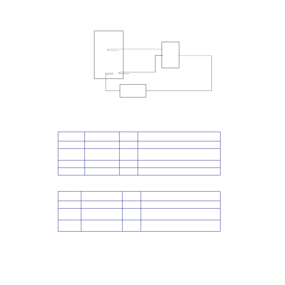
Figure 3.11 Example Application Using Cas-
cade Control
Table 3.10
Parameter Settings for the Primary
Loop in the Cascade Example
Table 3.11
Parameter Settings for the Second-
ary Loop in the Cascade Example
Menu
Parameter
Value
Comment
(none)
Set point
150˚F
Desired temperature at the inner thermocouple.
Control
Ht prop band
10
As the input drops 10°F, the output increases to
100 percent.
Control
Ht integral
0
Only proportional control is used.
Control
Ht derivative
0
Only proportional control is used.
Menu
Parameter
Value
Comment
Cascade
Cascade prim loop
1
Loop 1 is the primary loop.
Cascade
Cascade low SP
150˚F
When the primary loop’s output is 0 percent,
the secondary loop’s set point is 150°F.
Cascade
Cascade high SP
190˚F
When the primary loop output is 100 percent,
the secondary channel set point is 190°F.
CPC400
Water
Power
Controller
Loop 2 PID Output
Heater
Loop 1 Input
Process Variable
Loop 1: Primary Cascade Loop
Loop 2: Secondary Cascade Loop
Loop 2 Input
Process Variable
Outer
Thermocouple
Inner Thermocouple