Figure 2.21—digital output wiring 33 – Watlow CPC400 User Manual
Page 47
CPC400 Series User’s Guide
Chapter 2: Installation
Doc. 0600-2900-2000
Watlow Anafaze
33
Table 2.3
Digital Output States and Values
Stored in the Controller
1
Read and write these values through serial communications and Log-
icPro programs.
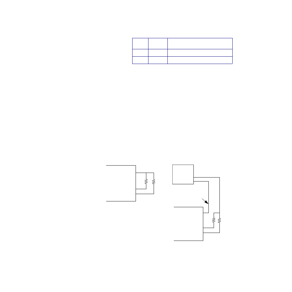
All digital outputs sink current to controller common when
on. The load may powered by the 5V
Î
(dc) supplied by the
controller at the TB50, or by an external power supply.
When using an external power supply, bear in mind:
•
The CPC400 power supply available from Watlow
Anafaze includes a 5V
Î
(dc) supply. When using it to
supply output loads, connect the 5V
Î
(dc) common to
the 15V
Î
(dc) common at the power supply.
•
Do not exceed +24 volts.
•
If you connect the external load to earth ground, or if
you cannot connect it as shown in Figure 2.21, then
use a solid-state relay.
The outputs conduct current when they are on. The maxi-
mum current sink capability is 60 mA at 24V
Î
(
dc). The
outputs cannot “source” current to a load.
Figure 2.21 Digital Output Wiring
State
Value
1
Description
Off
0
Open circuit
On
1
Sinking current to controller common
Digital Output 1
Digital Output 2
Control Common
+5V
Î
dc
Loads
Digital Output 1
Digital Output 2
Using External Power Supply
Do not connect
External
Power
+
-
TB50 or TB18
Using Internal Power Supply
Loads
Supply
TB50 or TB18
to earth ground or
equipment ground