Rtd input connections – Watlow CPC400 User Manual
Page 43
CPC400 Series User’s Guide
Chapter 2: Installation
Doc. 0600-2900-2000
Watlow Anafaze
29
Use 18 or 20 AWG (0.5 or 0.75 mm
2
) for all thermocouple
inputs. Most thermocouple wire is solid, unshielded wire.
When using shielded wire, ground one end only.
Figure 2.15 Thermocouple Connections
CAUTION!
Connect the earth ground terminal on TB2 to a
good earth ground, but do not connect the analog
common to earth ground. The CPC400 uses a
floating analog common for sensor measure-
ments. The noise protection circuits on the sen-
sor inputs function correctly only if the controller
is correctly installed. See Ground Loops on page
23.
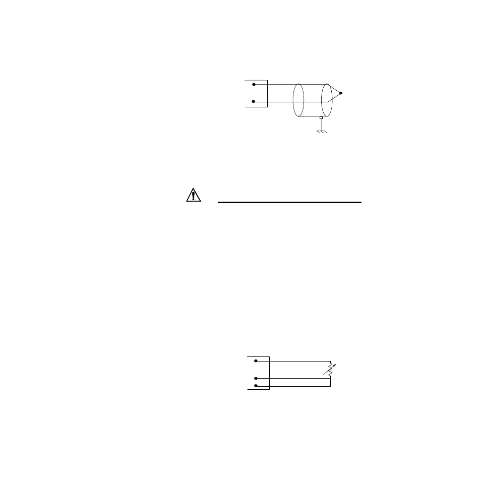
RTD Input Connections
RTD input requires scaling resistors. Watlow Anafaze rec-
ommends that you use a 100
Ω
, three-wire platinum RTD
to prevent reading errors due to cable resistance. If you use
a two-wire RTD, jumper the negative input to common. If
you must use a four-wire RTD, leave the fourth wire uncon-
nected.
Figure 2.16 RTD Connections
White
Red
Type J
CH IN+
CH IN-
Shield (if present)
Earth Ground
at Process End
Thermocouple
100
Ω
RTD
IN +
IN -
Com
CH
CH