Input wiring recommendations, Thermocouple connections, Figure 2.14—cpc400 connector locations 28 – Watlow CPC400 User Manual
Page 42
Chapter 2: Installation
CPC400 Series User’s Guide
28
Watlow Anafaze
Doc. 0600-2900-2000
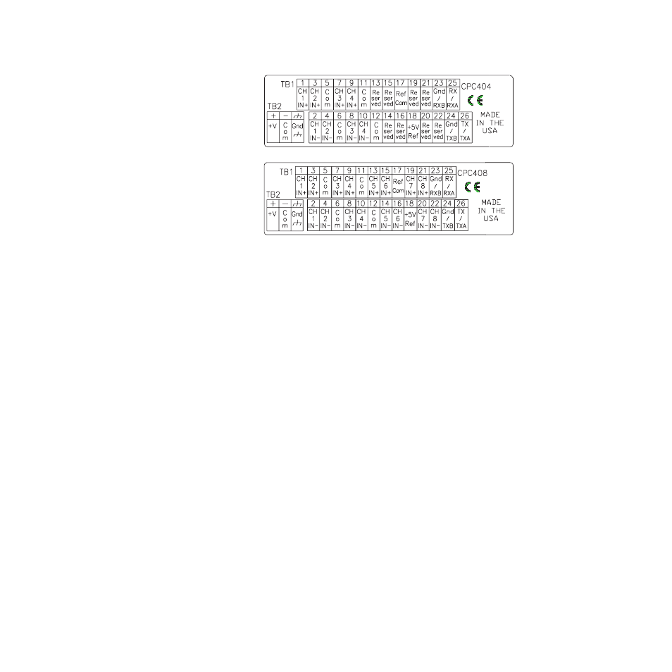
Figure 2.14 CPC400 Connector Locations
Input Wiring Recommendations
Use multicolored stranded shielded cable for analog inputs.
Watlow Anafaze recommends that you use 20 AWG wire
(0.5 mm
2
). If the sensor manufacturer requires it, you can
also use 24 or 22 AWG wiring (0.2 mm
2
). Most inputs use a
shielded twisted pair; some require a three-wire input.
The controller accepts the following inputs without any
special scaling resistors:
•
J, K, T, S, R, B and E thermocouples.
•
Process inputs with ranges between -10 and +60 mV.
To avoid thermocouple open alarms on unused inputs, ei-
ther set the Input type parameter to skip or jumper the in-
put.
Thermocouple Connections
Connect the positive lead of the thermocouple to the IN+
terminal for one of the loops, and connect the negative lead
to the corresponding IN- terminal.
- 12LS Controller (111 pages)
- 8LS Controller (140 pages)
- 8PID Controller (55 pages)
- Addendum to EZwarePlus (50 pages)
- ANASCAN (62 pages)
- ANASOFT (95 pages)
- ANAWIN 2 (154 pages)
- ANAWIN 3 (23 pages)
- Calibrating Watlow Series 988 Family Process Controls (19 pages)
- CAS (98 pages)
- CAS200 (124 pages)
- CLS (180 pages)
- CLS200 (251 pages)
- CLS200, MLS300 and CAS200 (92 pages)
- Control Console (12 pages)
- DIN-A-MITE Style A (9 pages)
- DIN-A-MITE Style B (14 pages)
- DIN-A-MITE Style C (22 pages)
- DIN-A-MITE Style D (9 pages)
- DIN-Mount Adapter Instruction Sheet, Rev A (1 page)
- Dual DAC (4 pages)
- EM Gateway (28 pages)
- E-Safe Hybrid Relay Rev B (4 pages)
- E-SAFE II Hybrid Power Switch (4 pages)
- EZwarePlus Programming (264 pages)
- EZ-ZONE PM (111 pages)
- EZ-ZONE PM PID (125 pages)
- EZ-ZONE PM Express Limit (34 pages)
- EZ-ZONE PM Express (35 pages)
- EZ-ZONE PM Integrated Controller (181 pages)
- EZ-ZONE RM Limit Module Rev C (127 pages)
- EZ-ZONE RMA Modul (79 pages)
- EZ-ZONE RMC (236 pages)
- EZ-ZONE RME (124 pages)
- EZ-ZONE RMH (161 pages)
- EZ-ZONE RUI/Gateway (62 pages)
- EZ-ZONE RM-Scanner-Modul (140 pages)
- EZ-ZONE ST (97 pages)
- F4 External Event Board - Rev.B (2 pages)
- HG Series Mercury Displacement Relay (6 pages)
- LogicPro (296 pages)
- Mercury Relay or MDR Retrofit (13 pages)
- MICRODIN (24 pages)
- MICRODIN (106 pages)