Mounting the power supply, Figure 2.9—cpc400 power supply mounting bracket 18 – Watlow CPC400 User Manual
Page 32
Chapter 2: Installation
CPC400 Series User’s Guide
18
Watlow Anafaze
Doc. 0600-2900-2000
Mounting the Power Supply
If you use your own power supply for the CPC400, refer to
the power supply manufacturer’s instructions for mounting
information. Choose a Class 2 power supply that supplies
an isolated, regulated 12 to 24V
Î
(
dc) at 1 A.
Mounting Environment
Leave enough clearance around the power supply so that it
can be removed.
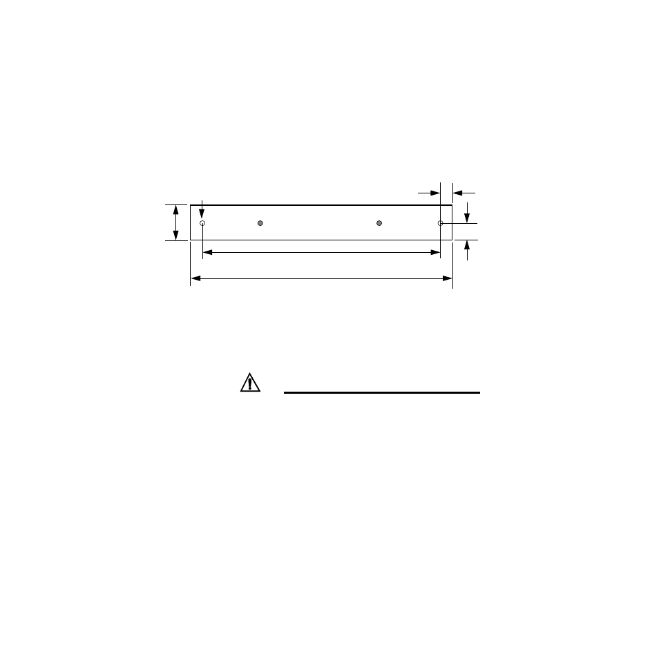
Figure 2.9
CPC400 Power Supply Mounting
Bracket
Mounting Steps
CAUTION!
When attaching the bracket to the power supply,
use screws that are no longer than 1/4-inch (6
mm) long. Longer screws may extend too far into
the power supply and short to components, dam-
aging the power supply.
1.
Attach the bracket to the power supply using the two
center holes in the bracket.
2.
Choose a location with enough clearance to remove the
power supply and bracket.
3.
Mark the bracket’s two outer holes for mounting.
4.
Drill and tap the two mounting holes. The bracket
holes accept up to #10 (4.5 mm) screws.
5.
Mount the power supply on the panel.
6.
Tighten the screws.
7.5 inches
(191 mm)
8.1 inches
(206 mm)
1.4 inch
(36 mm)
0.3 inch
(8 mm)
0.7 inch
(18 mm)
2 Holes for #10 (4.5 mm)
Bolts or Screws