Wiring the power supply, Table 2.2—power connections 24 – Watlow CPC400 User Manual
Page 38
Chapter 2: Installation
CPC400 Series User’s Guide
24
Watlow Anafaze
Doc. 0600-2900-2000
Wiring the Power Supply
WARNING!
Use a power supply with a Class 2 rating only. UL
approval requires a Class 2 power supply.
Connect power to the controller before any other connec-
tions, This allows you to ensure that the controller is work-
ing before any time is taken installing inputs and outputs.
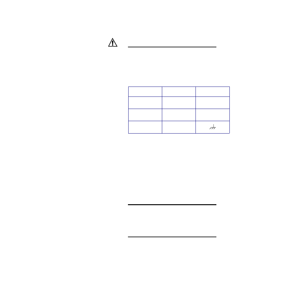
Table 2.2
Power Connections
1.
Connect the dc common terminal on the power supply
to the dc common (-) terminal on CPC400 TB2.
2.
Connect the positive terminal on the power supply to
the dc positive (+) terminal on CPC400 TB2.
3.
If using an isolated dc output or another power supply
to power the loads, connect the dc common of the sup-
ply powering the loads to the dc common of the supply
powering the controller.
4.
Use the ground connector on TB2 for chassis ground.
This terminal is connected to the CPC400 chassis and
must be connected to earth ground.
5.
Connect 120/240V
Å
(
ac) power to the power supply.
NOTE!
Connect the dc common of the power supply
used for loads to the dc common of the supply
powering the controller. If the supplies are not ref-
erenced to one another, the controller’s outputs
will not be able to switch the loads.
NOTE!
When making screw terminal connections, tight-
en to 4.5 to 5.4 in.-lb. (0.5 to 0.6 Nm).
Function
Power Supply
CPC400 TB2
DC Power
(Controller)
+12 to 24V
Î
(dc)
+
DC Common
12 to 24V
Î
(dc)
Common
-
Earth Ground
Ground