Proface AGP3500 - 10.4 DIO HMI" User Manual
Page 235
GP3000 Series Hardware Manual
9-26
(4)
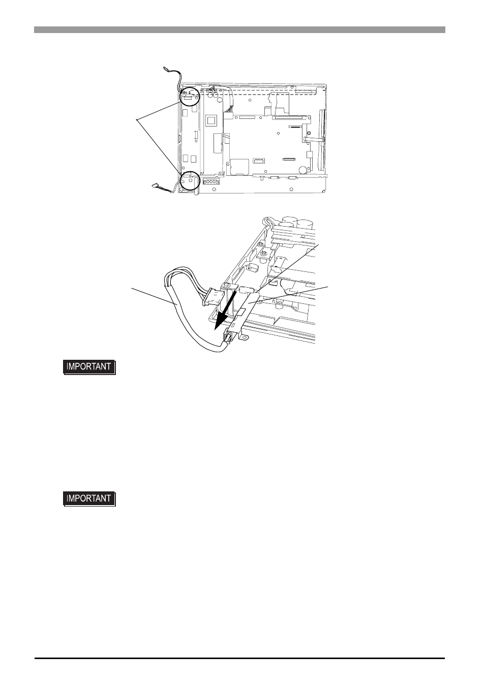
Insert shuttle driver to circular hole, and remove backlight setscrew. There are two circular hole.
(5)
Drawn out the cable in the direction of an arrow. Creep out backlight unit from backlight unit slot.
(6)
Insert a new backlight unit in backlight unit slot.
Secure the backlight setscrew. The necessary torque is 0.147N
•m. (The procedure of opposite to proce-
dure 4.)
(7)
Insert the cable to backlight connector.
Secure the cable with the cable clamp.
(The procedure of opposite to procedure 3.)
(8)
Return the rear face cover to the original position, and secure the cover in place using the mounting
screws (6). The necessary torque is 0.5N
•m
• Replace backlight the whole backlight unit.
• Be sure the cable is inserted completely into the backlight connector. Failure to do so
may cause arcing, which can damage the connector.
• Backlight has used 1 each of top and bottom LCD. The case of exchange 2 please
exchange simultaneously.
Shuttle driver entry
Backlight Unit
Backlight Unit slot
Cable
- AGP3400 - 7.5 DIO HMI" AGP3300 - 5.7 DIO HMI" AGP3600 - 12.1 FLEX Network HMIs" AGP3500 - 10.4 FLEX Network HMI" AGP3400 - 7.5 FLEX Network HMI" AGP3600 - 12.1 CANopen HMI" AGP3500 - 10.4 CANopen HMI" AGP3400 - 7.5 CANOpen HMI" AGP3300 - 5.7 CANopen HMI" AGP3300H - 5.7 Handheld HMIs" AGP3750 - 15 Multi-Media HMI" AGP3650 - 12.1 Multi-Media HMIs" AGP3550 - 10.4 Multi-Media HMIs" AGP3450 - 7.5 Multi-Media HMI" AGP3360 - 5.7 Multi-Media HMI" AST3300 - 5.7 Basic HMI" AST3200 - 3.8 Basic HMI" AGP3600 - 12.1 Standard HMIs" AGP3500 - 10.4 Standard HMIs" AGP3400 - 7.5 Standard HMI" AGP3300 - 5.7 Standard HMI" AGP3200 - 3.8 Standard HMI"