Proface AGP3500 - 10.4 DIO HMI" User Manual
Page 234
Chapter 9 Maintenance
9-25
(1)
Unplug the power cord from the main power supply.
(2)
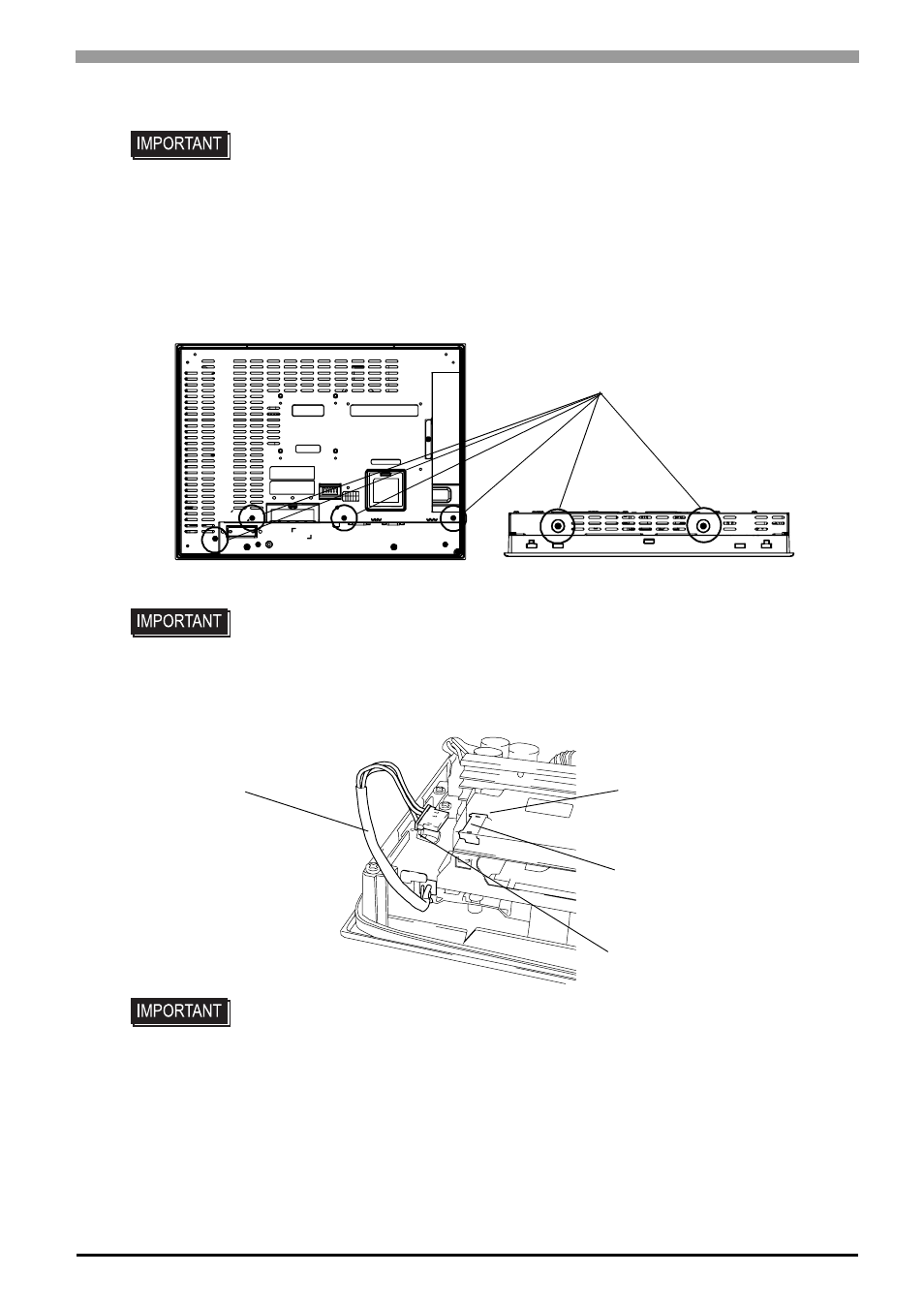
Remove the retaining screws (6) on the rear cover, and detach the cover from the main unit.
(3)
Pull out cable from inverter insulating sheet, and remove from cable clump.
Remove cable from backlight connector on inverter circuit board.
• Remove the GP unit from the equipment to which the unit has been incorporated,
and work with the GP unit with the display surface facing downward. Be sure to
perform the backlight changeover on a flat, level surface. This will prevent damage
to the GP unit and the accidental cutting of any of its power cord.
• Be sure to protect the display surface to prevent damage during the operations.
• Do not let the attachment screws fall inside the GP, or lose them.
• A hot circuit board chassis can burn you. Be sure the chassis has cooled completely
prior to replacing the backlights.
Retaining screws
Rear
Upper
Cable
Cable clump
Backlight connector
Inverter insulating sheet
- AGP3400 - 7.5 DIO HMI" AGP3300 - 5.7 DIO HMI" AGP3600 - 12.1 FLEX Network HMIs" AGP3500 - 10.4 FLEX Network HMI" AGP3400 - 7.5 FLEX Network HMI" AGP3600 - 12.1 CANopen HMI" AGP3500 - 10.4 CANopen HMI" AGP3400 - 7.5 CANOpen HMI" AGP3300 - 5.7 CANopen HMI" AGP3300H - 5.7 Handheld HMIs" AGP3750 - 15 Multi-Media HMI" AGP3650 - 12.1 Multi-Media HMIs" AGP3550 - 10.4 Multi-Media HMIs" AGP3450 - 7.5 Multi-Media HMI" AGP3360 - 5.7 Multi-Media HMI" AST3300 - 5.7 Basic HMI" AST3200 - 3.8 Basic HMI" AGP3600 - 12.1 Standard HMIs" AGP3500 - 10.4 Standard HMIs" AGP3400 - 7.5 Standard HMI" AGP3300 - 5.7 Standard HMI" AGP3200 - 3.8 Standard HMI"