Proface AGP3500 - 10.4 DIO HMI" User Manual
Page 227
GP3000 Series Hardware Manual
9-18
(5)
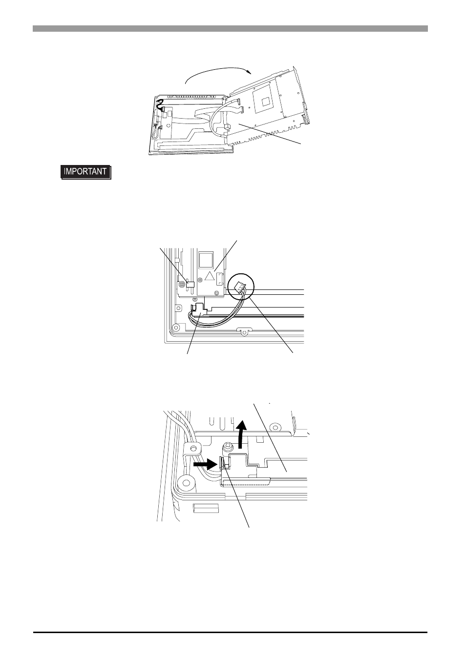
Open the circuit board chassis, it’s turn left to right.
(6)
Disconnect the Backlight Unit cable from the connector on the inverter board, and then remove the cable
from the cable clamp.
(7)
As shown here, push the backlight unit’s attachment clip to the right to release the backlight unit.
• A hot circuit board chassis can burn you. Be sure the chassis has cooled completely
prior to replacing the backlights.
Circuit board chassis
Connector
Inverter
Backlight Unit
for bottom
Cable Clamp
Backlight Unit
Hook
This manual is related to the following products:
- AGP3400 - 7.5 DIO HMI" AGP3300 - 5.7 DIO HMI" AGP3600 - 12.1 FLEX Network HMIs" AGP3500 - 10.4 FLEX Network HMI" AGP3400 - 7.5 FLEX Network HMI" AGP3600 - 12.1 CANopen HMI" AGP3500 - 10.4 CANopen HMI" AGP3400 - 7.5 CANOpen HMI" AGP3300 - 5.7 CANopen HMI" AGP3300H - 5.7 Handheld HMIs" AGP3750 - 15 Multi-Media HMI" AGP3650 - 12.1 Multi-Media HMIs" AGP3550 - 10.4 Multi-Media HMIs" AGP3450 - 7.5 Multi-Media HMI" AGP3360 - 5.7 Multi-Media HMI" AST3300 - 5.7 Basic HMI" AST3200 - 3.8 Basic HMI" AGP3600 - 12.1 Standard HMIs" AGP3500 - 10.4 Standard HMIs" AGP3400 - 7.5 Standard HMI" AGP3300 - 5.7 Standard HMI" AGP3200 - 3.8 Standard HMI"