Proface AGP3500 - 10.4 DIO HMI" User Manual
Page 217
GP3000 Series Hardware Manual
9-8
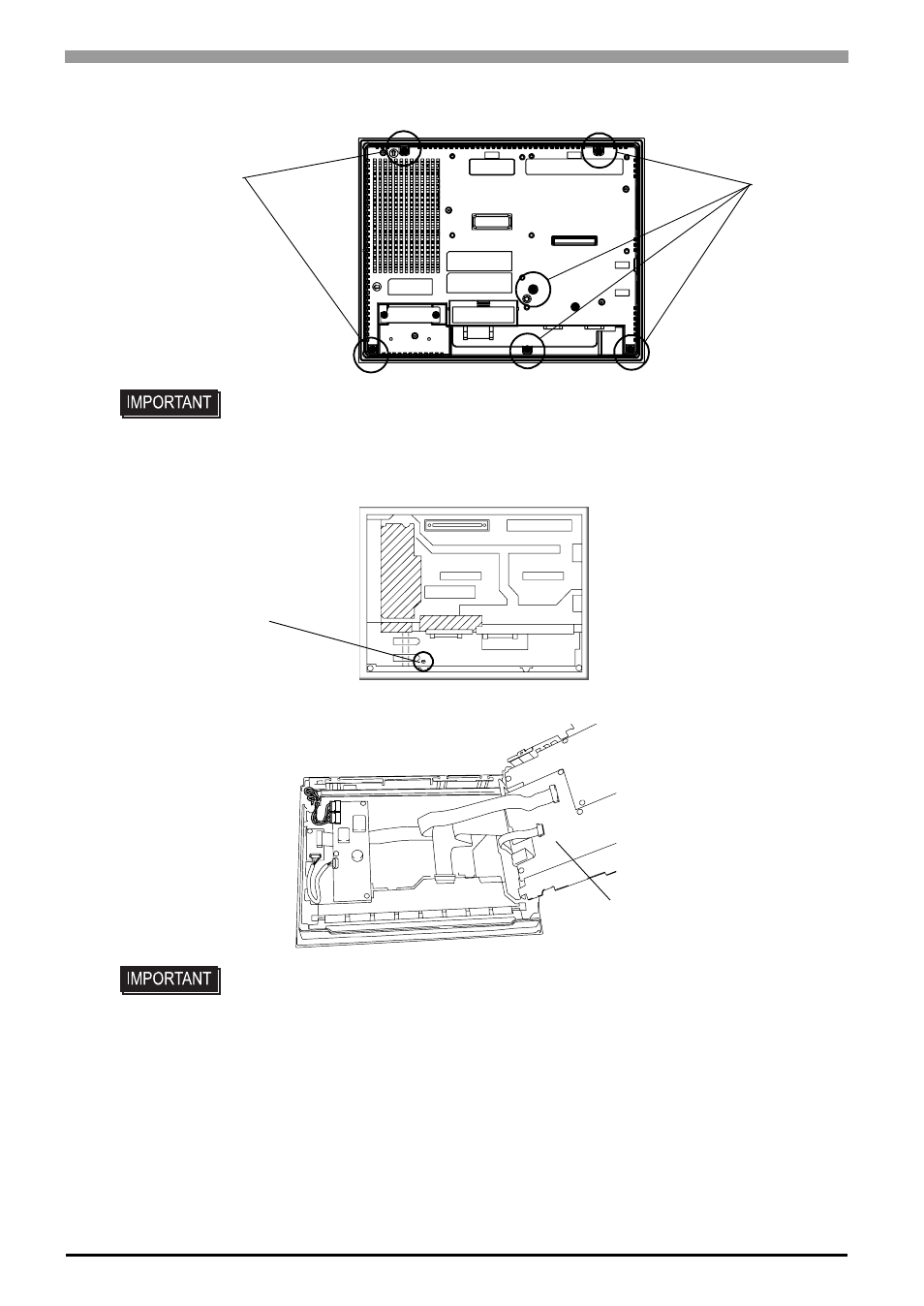
(2)
Remove the retaining screws (6) on the rear cover.
(3)
Open the rear cover carefully from the bottom of the unit to the top.
(4)
Remove the setscrew (1) on the circuit board chassis.
(5)
Open the circuit board chassis, it’s turn left to right.
• Do not let the attachment screws fall inside the GP, or lose them
• A hot circuit board chassis can burn you. Be sure the chassis has cooled completely
prior to replacing the backlights.
Screws
Screws
Setscrew
Circuit board chassis
This manual is related to the following products:
- AGP3400 - 7.5 DIO HMI" AGP3300 - 5.7 DIO HMI" AGP3600 - 12.1 FLEX Network HMIs" AGP3500 - 10.4 FLEX Network HMI" AGP3400 - 7.5 FLEX Network HMI" AGP3600 - 12.1 CANopen HMI" AGP3500 - 10.4 CANopen HMI" AGP3400 - 7.5 CANOpen HMI" AGP3300 - 5.7 CANopen HMI" AGP3300H - 5.7 Handheld HMIs" AGP3750 - 15 Multi-Media HMI" AGP3650 - 12.1 Multi-Media HMIs" AGP3550 - 10.4 Multi-Media HMIs" AGP3450 - 7.5 Multi-Media HMI" AGP3360 - 5.7 Multi-Media HMI" AST3300 - 5.7 Basic HMI" AST3200 - 3.8 Basic HMI" AGP3600 - 12.1 Standard HMIs" AGP3500 - 10.4 Standard HMIs" AGP3400 - 7.5 Standard HMI" AGP3300 - 5.7 Standard HMI" AGP3200 - 3.8 Standard HMI"