Connecting the i/o cable, 2 connecting the i/o cable, Pio pattern 0 positioning mode [standard type – IAI America SCON-C User Manual
Page 79
61
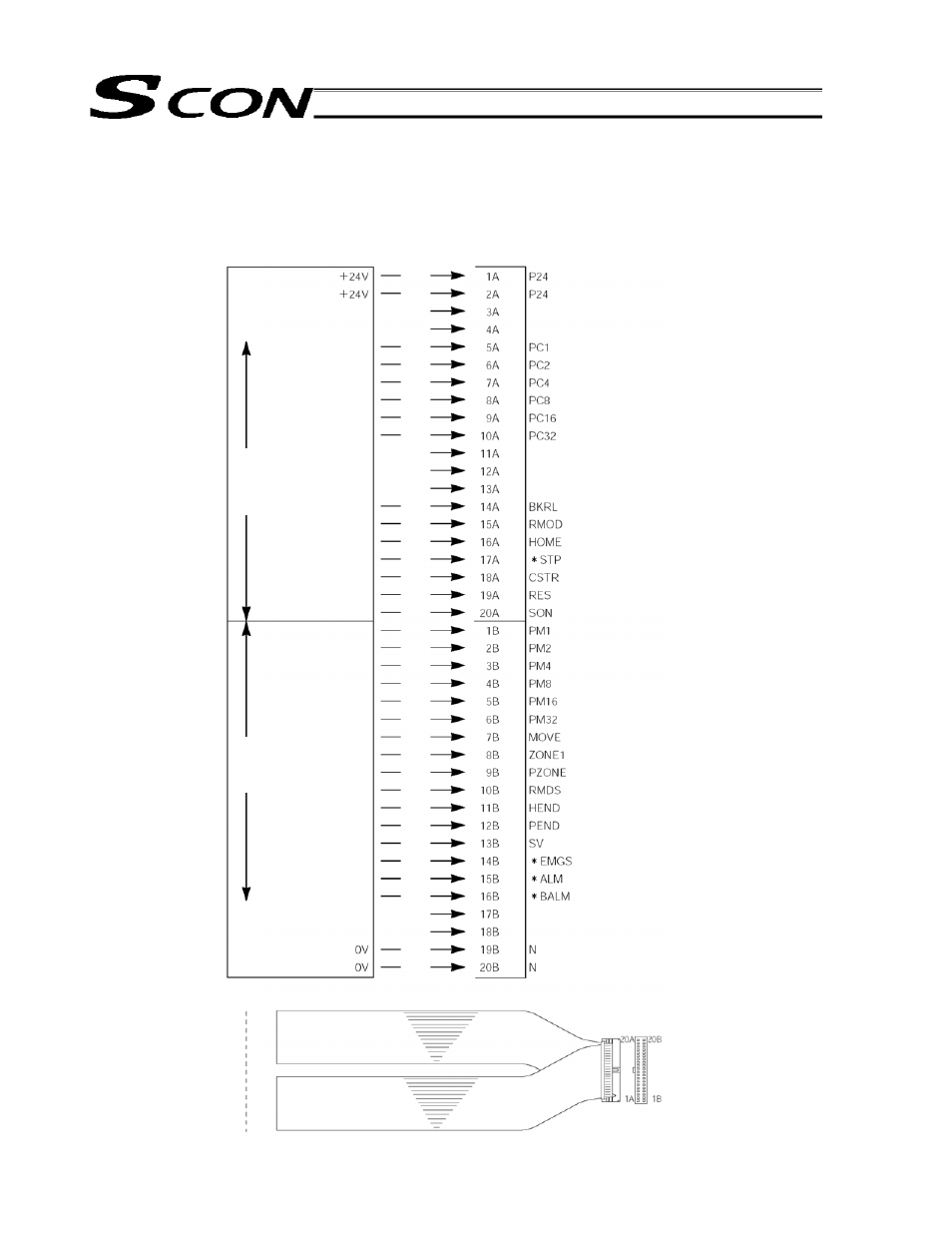
1.2 Connecting the I/O Cable
PIO pattern 0 Positioning mode [Standard type]
Black 4
Brown 1
Brown-1
Red-1
Orange-1
Yellow-1
Green-1
Blue-1
Purple-1
Gray-1
White-1
Black-1
Brown-2
Red-2
Orange-2
Yellow-2
Green-2
Blue-2
Purple-2
Gray-2
White-2
Black-2
Brown-3
Red-3
Orange-3
Yellow-3
Green-3
Blue-3
Purple-3
Gray-3
Wihte-3
Black-3
Brown-4
Red-4
Orange-4
Yellow-4
Green-4
Blue-4
Purple-4
Gray-4
White-4
Black-4
Host system
Controller end
PIO (signal abbreviation)
Outpu
t side
Inpu
t side
Command position 1
Command position 2
Command position 4
Command position 8
Command position 16
Command position 32
Brake release
Operating mode
Home return
Pause
Start
Reset
Servo on
Completed position 1
Completed position 2
Completed position 4
Completed position 8
Completed position 16
Completed position 32
Moving
Zone 1
Position zone
Operating mode status
Home return completion
Position complete
Servo-on status
Emergency stop status
Alarm
Battery alarm
(Note)
*STP, *ALM, *EMGS and *BALM
are negative-logic signals.
Bottom
Top