IAI America SCON-C User Manual
Page 54
36
[2] Wiring and setting of safety circuit
[1] Power
supply
If a safety circuit is configured using safety relays and contactors of 24 V specifications, it is recommended to
use a separate power supply from the power supply for controllers of 24 V specifications (ACON, PCON etc.).
It can be configured using the common power supply between the two, but breakage may occur when falsely
wired.
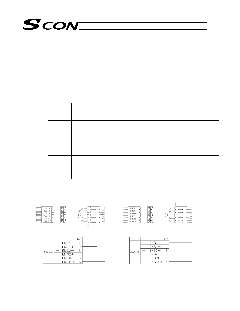
[2] System I/O connector specification
Connector used: MCDN1.5/6-G1-3.5P26THR (PHOENIX CONTACT)
Cable side connector (accessory: initial wiring already conducted *):
FMC1.5/6-ST-3.5 (PHOENIX CONTACT)
Supported wire thickness: AWG24-16, recommended stripped wire length: 7 mm
Pin No.
Signal name
Explanation
1 EMG1-
2 EMG1+
Emergency stop contact 1
(30 VDC or less, 100 mA or less)
3 EMG2-
4 EMG2+
Emergency stop contact 2
(30 VDC or less, 100 mA or less)
5
EMGIN
Emergency stop detection input
Upper side
(EMG side)
6
EMGOUT
24 V power supply output for emergency stop detection input
7 ENB1-
8 ENB1+
Enable contact 1
(30 VDC or less, 100 mA or less)
9 ENB2-
10 ENB2+
Enable contact 2
(30 VDC or less, 100 mA or less)
11
ENBIN
Enable detection input
Lower side
(ENB side)
12
ENBOUT
24 V power supply output for enable detection input
* Connectors on the cable side are attached under conditions where initial wiring has been conducted.
In order to support each category, remove the initial wiring and wire your safety circuit.
Upper side (EMG) connector
Lower side (ENB) connector
Wiring Color
Signal
Yellow
Yellow
Yellow
Yellow
Wiring
Color
Signal
Yellow
Yellow
Yellow
Yellow