Chapter 2 positioner mode, I/o signal control and signal functions, Chapter 2 – IAI America SCON-C User Manual
Page 70: Positioner mode, Pio patterns and signal assignments, 1 pio patterns and signal assignments
52
Chapter 2 Positioner Mode
1. I/O Signal Control and Signal Functions
1.1 PIO Patterns and Signal Assignments
This controller provides six PIO pattern types to meet the needs of various applications.
To select a desired type, set a corresponding value from 0 to 5 in parameter No. 25 (PIO pattern selection).
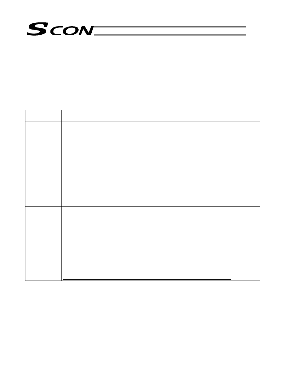
The features of each PIO pattern are explained below:
Parameter No.
25 setting
Feature of PIO pattern
0
Positioning mode [Standard type]
A basic type supporting 64 positioning points and two zone outputs.
* How to set zone boundaries within which to output a zone signal:
Zone boundaries are set using parameter Nos. 1 and 2 for one zone output, and in the position
table for another zone output.
1
Teaching mode [Teaching type]
In this type, 64 positioning points and one zone output (boundaries are set in the position table)
are supported.
In addition to the normal positioning mode, the user can also select the teaching mode in which
the actuator can be jogged via I/Os and the current actuator position can be written to a
specified position.
(Note) Positions can be rewritten by approximately 100,000 times.
2
256-point mode [256-point type]
The number of positioning points is increased to 256, so only one zone output is available
(boundaries are set in the position table).
3
512-point mode [512-point type]
The number of positioning points is increased to 512, so no zone output is available.
4
Solenoid valve mode 1 [7-point type]
The number of positioning points is limited to seven, but separate direct command inputs and
position complete outputs are provided.
PLC ladder sequence circuits can be designed easily.
5
Solenoid valve mode 2 [3-point type]
Use of the controller as an air cylinder is assumed in this type.
The function of position complete output signals is different from how these signals function in
the 7-point type. These signals not only indicate that the position specified by each move
command “has been reached,” but the also function as a limit switch. This means that the
signals will turn ON even when the actuator is moved by hand.
Take note that incremental positioning commands are not supported in this mode.