IAI America SCON-C User Manual
Page 183
165
(2) Command pulse mode
User parameter No. 63, “Command-pulse input mode”
Name Symbol Unit Input
range
Default setting
(reference)
Command-pulse
input mode
CPMD
-
0 to 2
1
Set a desired pulse-train input pattern for command pulse input (PP•/PP, NP•/NP).
* Whether to apply the positive logic or negative logic is set in accordance with (3), “Input polarity in the
command pulse mode.”
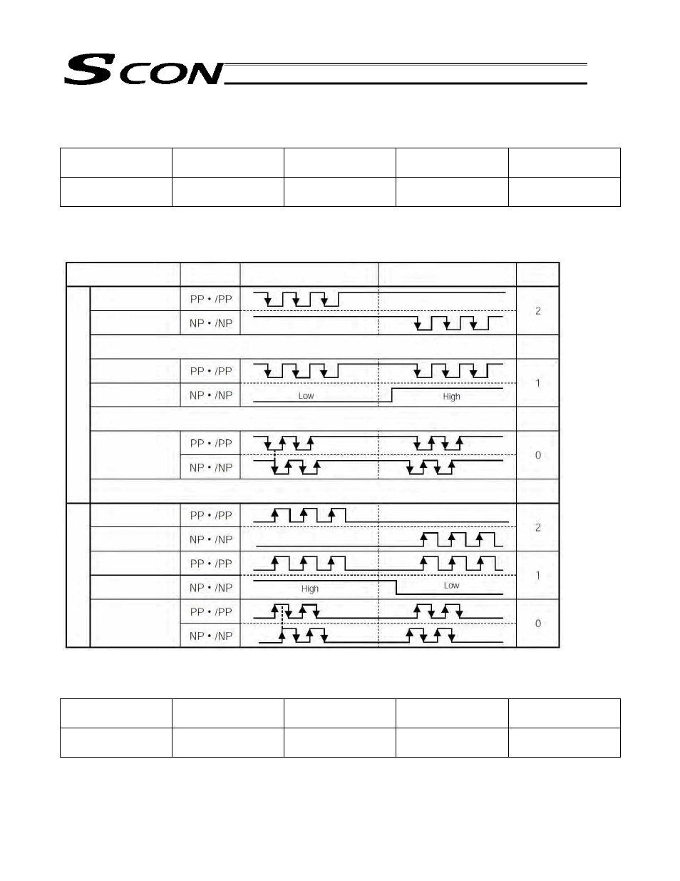
(3) Input polarity in the command pulse mode
User parameter No. 64, “Command-pulse input mode polarity”
Name Symbol Unit Input
range
Default setting
(reference)
Command-pulse
input mode polarity
POLE
-
0 to 1
0
Setting
Positive logic: 0
Negative logic: 1
Command pulse-train
pattern
Forward Reverse
Neg
a
ti
ve lo
gic
P
osit
ive lo
gic
Forward pulse
train
A forward pulse train indicates motor revolutions in the forward direction, while a
reverse pulse train indicates motor revolutions in the negative direction.
Pulse train
Phase-A/B pulse
train
Phase-A/B x4 pulses with a 90
phase difference indicate motor revolutions and a
rotating direction.
Pulse train
Sign
Phase-A/B pulse
train
Input
terminal
Reverse pulse
train
Sign
Command pulses indicate motor revolutions, while a command sign indicates a
rotating direction.
Forward pulse
train
Reverse pulse
train