Wiring, External connection diagram, 1 external connection diagram – IAI America SCON-C User Manual
Page 165
147
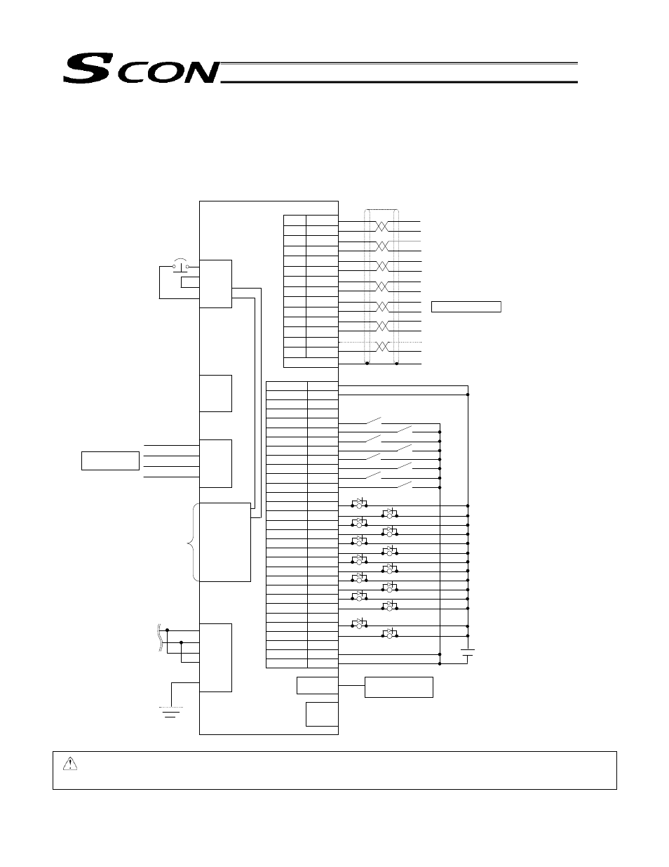
2. Wiring
2.1 External
Connection
Diagram
A wiring example in the pulse control mode is shown below.
Caution: To operate the actuator by allowing the controller to communicate with the PLC via I/O signals, be
sure to tilt the mode selector switch on the front panel of the controller to the “AUTO” position.
24 DCV
10%
SCON controller
Connected to teaching
pendant or PC
External EMG switch
Motor relay cable
CB-X-MA ***
Shield
Motor relay cable
CB-X2-PA***
Green
Red
White
Black
Black
White/Black
Red
White/Red
Green
White/Green
Yellow
White/Yellow
Brown
White/Brown
Blue
White/Blue
Gray
White/Gray
Not used
Not used
Optional shielded
I/O cable
24 V
24 V
Not used
Not used
SON
RES
HOME
TL
CSTP
DCLR
BKRL
RMOD
Not used
PWR
SV
INP
HEND
TLR
*ALM
*EMGS
RMDS
ALM1
ALM2
ALM4
ALM8
Not used
ZONE1
ZONE2
Regenerative unit (REU-1)
Power supply
Single-phase 100 V
Single-phase 200 V
Battery unit (not used)
Not used
0 V
0 V
S1
S2
EMG+
EMG-
PULSE
PP
/PP
NP
/NP
AFB
/AFB
BFB
/BFB
ZFB
/ZFB
GND
GND
1
2
3
4
5
6
7
8
9
10
11
12
13
14
CB-SC-PIOS020
I/O
RB+
RB-
PE
MOT
PE
U
V
W
1. (SGA)
2 (SGB)
3. (+5 V)
4. (ENB)
5. (EMGA)
6. (+24 V)
7. (GND)
8. (EMGB)
1A
2A
3A
4A
5A
6A
7A
8A
9A
10A
11A
12A
13A ~ 20A
1B
2B
3B
4B
5B
6B
7B
8B
9B
10B
11B
12B
13B, 14B
15B
16B
17B, 18B
19B
20B
L1
L2
L1C
L2C
NC
PE
BAT-
BAT+
ENC