Specifications, Basic specifications, 1 basic specifications – IAI America SCON-C User Manual
Page 27
9
2. Specifications
2.1 Basic
Specifications
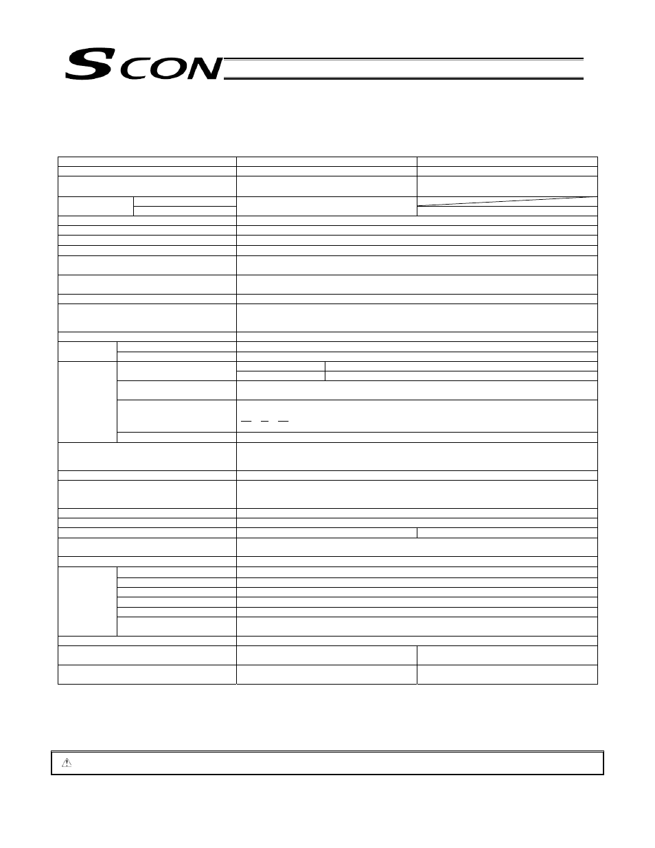
Item
Less than 400 W
400 W or more
Applicable motor capacity
20 W to 399 W
400 W to 750 W
Power-supply voltage
Single-phase 100 to 115 VAC
10%
Single-phase 200 to 230 VAC
10%
Single-phase 200 to 230 VAC
10%
100 VAC
Rush current
*1
200 VAC
20 A (control), 70 A (drive)
20 A (control), 80 A (drive)
Leak current
*2
3.0 mA (Primary side when noise filter is connected to the power supply line)
Heat output
30 W to 58 W
Power supply frequency
50/60 Hz
PIO interface power supply
*3
24 VDC
10% (Externally supplied)
Solenoid brake power supply
(in case of actuators equipped with brake)
24 VDC
10% 1 A (peak value)
(Externally supplied)
Resistance against temporary electric power
failure
10 ms (50 Hz), 8 ms (60 Hz)
Motor control method
Sine wave PWM vector current control
Supported encoders
Incremental serial encoder
Absolute serial encoder
ABZ (UVW) parallel encoder
Operation mode
Positioner mode/pulser-train control mode (Operation mode is switched with the DIP switch.)
Number of positions
512 points (maximum)
Positioner
mode
Inputs/outputs
16 dedicated input points / 16 dedicated output points
Differential pulse
MAX. 500 kpps
Input pulse frequency
Open-collector pulse
MAX. 200 kpps (Pulse converter AK-04 is required.)
Feedback pulse frequency
The maximum speed with differential pulse is 500 kpps (up to 109 kpps can be output linearly
following the speed of actuators).
Command pulse multiplier
(electronic gear: A/B)
A, B = 1 to 4096 (Parameter settings)
1
50
B
A
50
1
Pulse-train
mode
Dedicated I/O (PIO)
8 input points / 12 output points
Serial communication interface
RS485: 1 channel (conforming to Modbus protocol RTU/ASCII)
Speed: 9.6 kpps to 230.4 kpps
Control via serial communication is possible with the positioner mode.
I/O (PIO) cable length
10 m or less
Communication cable length
Total cable length shall be 100 m or less (RS485).
Length in case of Fieldbus specifications (CC-Link, DeviceNet, PROFIBUS) depends on each
Fieldbus specification.
Data input method
Teaching pendant, PC software
Protective functions
Overvoltage, motor overcurrent, motor overload, driver temperature error, encoder error, etc.
Air cooling method
Natural cooling
Forced cooling
Withstand voltage
Between primary and secondary: 1500 VAC, 1 minute
Between primary and FG:
1500 VAC, 1 minute
Insulation resistance
Between secondary and FG:
500 VDC 100 M
or more
Surrounding air temperature
0
C to 40C
Surrounding humidity
85%RH or less (no condensation)
Surrounding environment
(See the installation environment section.)
Storage ambient temperature
-10
C to 65C
Storage ambient humidity
90%RH or less (no condensation)
Environment
Vibration resistance
XYZ directions, 10 to 57 Hz, one side width 0.035 mm (continuous), 0.075 mm (intermittent)
57 to 150 Hz 4.9 m/s
2
(continuous), 9.8 m/s
2
(ongoing)
Protection class
IP20
Weight
Approximately 800 g (approximately 25 g more
in case of absolute specifications)
Approximately 1100 g (approximately 25 g more
in case of absolute specifications)
External dimension
58 (W) x 194 (H) x 121 (D)
(Installation pitch: 184)
72 (W) x 194 (H) x 121 (D)
(Installation pitch: 184)
*1 Rush current flows approximately 20 ms after turning the power supply on (guideline at 40
C).
*2 Leak power supply changes depending on the capacity of connected motor, cable length, and surrounding environment. If protection against leak
current is installed, measure leak current at installation location of leak current breaker.
*3 Power supply for I/O signals is not necessary if the controller is operated using field network (CC-Link, DeviceNet, PROFIBUS), gateway unit, or
SIO converter, without using PIO. In this case, set “1” (disabled) for parameter No. 74 (PIO power supply monitoring).
Caution: Position data, parameters, etc. are written in EEPROM. The number of writings is limited to approximately 100,000 times.