IAI America SCON-C User Manual
Page 29
11
[1] LED
indicators
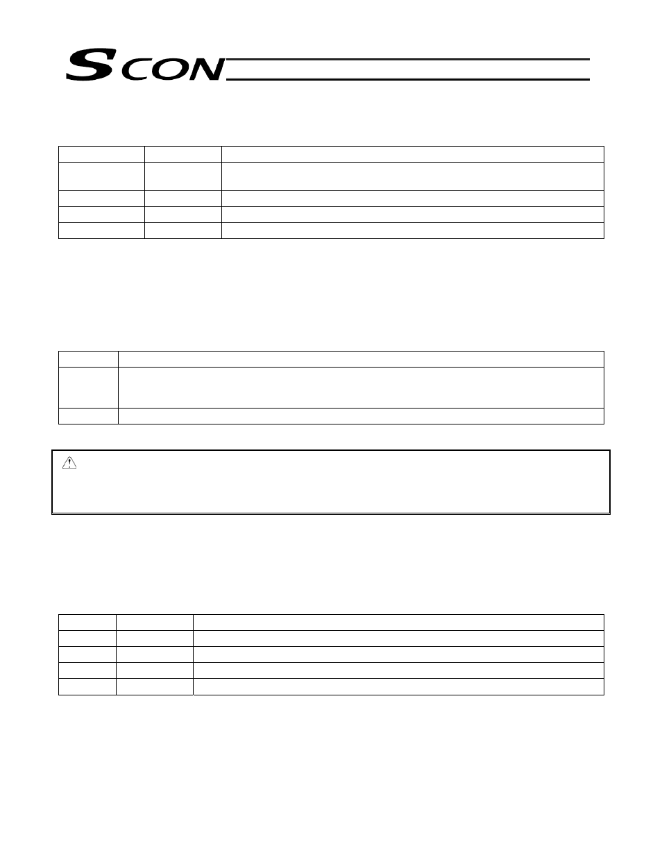
These LEDs indicate the condition of the controller.
Name Color
Description
PWR Green
This LED illuminates when the system has become ready (after the power has
been input and the CPU has started normally).
SV
Green
This LED illuminates when the servo has turned on.
ALM
Orange
This LED illuminates while an alarm is present.
EMG
Red
This LED illuminates while an emergency stop is actuated.
[2] Rotary
switches
These switches are used to set the controller address.
If two or more controllers are linked via serial communication, set a unique address for each controller.
* The address set by the switches will become effective after the power is reconnected or software is reset.
[3] Piano
switches
These switches are used to set the various modes of the controller system.
Name Description
1
Operation mode selector switch
OFF: Positioner mode, ON: Pulse-train control mode
* The mode set by the switch will become effective after the power is reconnected.
2
Reserved by the system. (This switch must be set to “OFF.”)
Caution: When controlling the SCON controller via serial communication, always set the controller in the
“positioner mode” (piano switch 1: OFF).
If it happens to be in the “pulse-train mode” by mistake, the SCON controller may operate
erratically because it is operated according to the “pulse-train mode” parameters.
[4] System I/O connector
This connector is used to connect the emergency stop switch, etc.
Connector (controller side): MC1.5/4-G-3.5 (Phoenix Contact)
Connector (plug-in side):
FMC1.5/4-ST-3.5 (Phoenix Contact)
Applicable cable diameter: 0.2 to 1.3 mm
2
(AWG24 to 16)
Pin No.
Signal name
Description
1
S1
Emergency-stop switch contact output for teaching pendant
2
S2
Emergency-stop switch contact output for teaching pendant
3
EMG+
24-V output for emergency stop
4
EMG-
Emergency sop input