IAI America SCON-C User Manual
Page 111
93
Item Air
cylinder
SCON
Position check
upon power
ON
Determined by an
external detection sensor,
such as a reed switch.
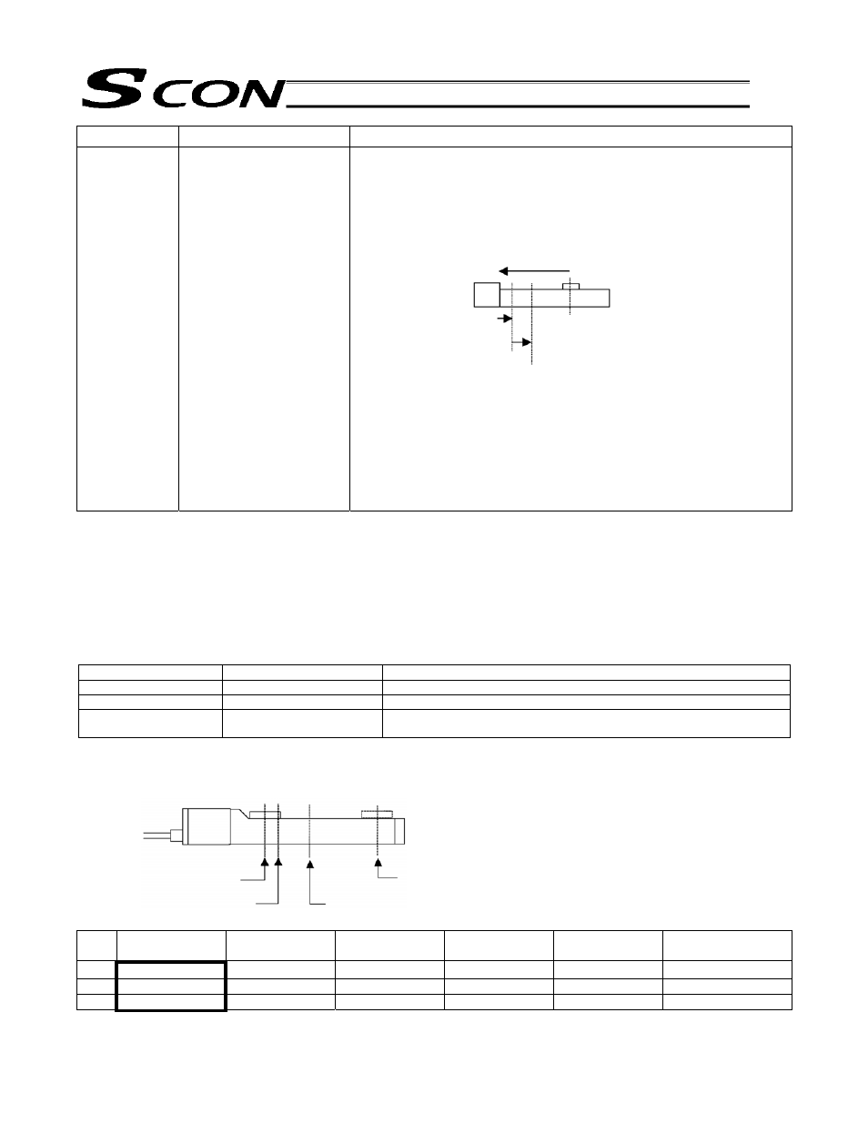
Immediately after the power is turned on, the controller cannot
identify the current position because the mechanical coordinates
have been lost.
Accordingly, a rear end command must always be executed after the
power is turned on, to establish the coordinates.
The actuator will perform home-return operation first, and then move
to the rear end.
[1] The actuator moves at the home return speed toward the
mechanical end on the motor side.
[2] The actuator contacts the mechanical end and turns back, and
then stops temporarily at the home position.
[3] The actuator moves to the rear end at the speed set in the
[Speed] field of the position table.
(Note) Pay attention not to allow any obstacle in the travel path of
the actuator during home return.
The relationship of each movement command input/position detected and corresponding position number is
shown below.
The input/output signals are given easy-to-identify names by following the naming convention of air-cylinder
switches.
However, the target position is determined by the value set in the [Position] field for each position number.
Therefore, changing the magnitude relationships of settings under position Nos. 0, 1 and 2 will change the
meanings of input/output signals.
For this reason, it is recommended that you always use the signals under their names defined in this manual,
unless doing so presents problem, so that the signals have the same meanings at all time.
Input signal
Output signal
Target position
Rear end move (ST0)
Rear end detected (LS0)
Value set in the [Position] field for position No. 0 Example) 5 mm
Front end move (ST1)
Front end detected (LS1)
Value set in the [Position] field for position No. 1 Example) 390 mm
Intermediate point move
(ST2)
Intermediate point detected
(LS2)
Value set in the [Position] field for position No. 2 Example) 200 mm
Positioning relationship on the ROBO Cylinder
An example of a slider type with a stroke of 400 mm is explained.
Position table (Enter in the fields indicated in bold)
No.
Position
[mm]
Speed
[mm/s]
Acceleration
[G]
Deceleration
[G]
Push
[%]
Positioning band
[mm]
0 5.00 500.00 0.30 0.30
0 0.10
1 390.00
500.00
0.30 0.30
0 0.10
2 200.00
500.00
0.30 0.30
0 0.10
[1]
[2]
[3]
Home position
Rear and position
Power is turned on
here.
Home position (0 mm)
Rear end detected
(5 mm)
Front end detected
(390 mm)
Intermediate point detected
(200mm)
[Motor side]
[Counter-motor side]