IAI America ERC2 User Manual
Page 88
4. Electrical Specifications
65
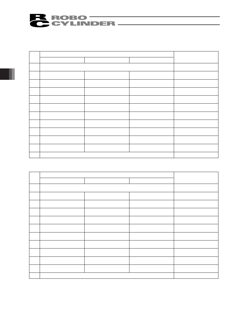
[6] PIO connection terminal block (TB3)
A PLC connection port. Detailed signal specifications are shown below.
[1] RCB-TU-PIO-A/B (When the control board is of the NPN specification)
PIO pattern
TB3
0 (8-point type)
1 (3-point type)
2, 3 (16-point type)
Remarks
1
Input common (In-COM) 24 [V]
(Note 1)
LED 11 illuminates when
24 V is supplied.
2
Command position 1 (PC1) Move to rear end (ST0)
Command position 1 (PC1) LED1 illuminates when this
signal turns ON.
3
Command position 2 (PC2) Move to front end (ST1)
Command position 2 (PC2) LED2 illuminates when this
signal turns ON.
4
Command position 4 (PC4) Move to intermediate point
(ST2)
Command position 4 (PC4) LED3 illuminates when this
signal turns ON.
5
Home return (HOME)
Command position 8 (PC8) LED4 illuminates when this
signal turns ON.
6
Start (CSTR)
Start (CSTR)
LED5 illuminates when this
signal turns ON.
7
*Pause (*STP)
*Pause (*STP)
*Pause (*STP)
LED6 illuminates when this
signal turns ON.
8
Position complete (PEND) Rear end (PE0)
Position complete (PEND) LED7 illuminates when this
signal turns ON.
9
Home-return completion
(HEND)
Front end (PE1)
Home-return completion
(HEND)
LED8 illuminates when this
signal turns ON.
10 Zone output (ZONE)
Intermediate point (PE2)
Zone output (ZONE)
LED9 illuminates when this
signal turns ON.
11 *Alarm (*ALM)
*Alarm (*ALM)
*Alarm (*ALM)
LED10 illuminates when
this signal turns ON.
12 Output common (Out-COM) 0 [V]
(Note 1)
(Note 1) The input common and output common become 0 [V] and 24 [V], respectively, in the PNP specification.
[2] RCB-TU-PIO-AP/BP (When the control board is of the PNP specification)
PIO pattern
TB3
0 (8-point type)
1 (3-point type)
2, 3 (16-point type)
Remarks
1
Input common (In-COM) 0 [V]
(Note 2)
LED 11 illuminates when
24 V is supplied.
2
Command position 1 (PC1) Move to rear end (ST0)
Command position 1 (PC1) LED1 illuminates when this
signal turns ON.
3
Command position 2 (PC2) Move to front end (ST1)
Command position 2 (PC2) LED2 illuminates when this
signal turns ON.
4
Command position 4 (PC4) Move to intermediate point
(ST2)
Command position 4 (PC4) LED3 illuminates when this
signal turns ON.
5
Home return (HOME)
Command position 8 (PC8) LED4 illuminates when this
signal turns ON.
6
Start (CSTR)
Start (CSTR)
LED5 illuminates when this
signal turns ON.
7
*Pause (*STP)
*Pause (*STP)
*Pause (*STP)
LED6 illuminates when this
signal turns ON.
8
Position complete (PEND) Rear end (PE0)
Position complete (PEND) LED7 illuminates when this
signal turns ON.
9
Home-return completion
(HEND)
Front end (PE1)
Home-return completion
(HEND)
LED8 illuminates when this
signal turns ON.
10 Zone output (ZONE)
Intermediate point (PE2)
Zone output (ZONE)
LED9 illuminates when this
signal turns ON.
11 *Alarm (*ALM)
*Alarm (*ALM)
*Alarm (*ALM)
LED10 illuminates when
this signal turns ON.
12 Output common (Out-COM) 24 [V]
(Note 2)
(Note 2) The input common and output common become 24 [V] and 0 [V], respectively, in the NPN specification.