IAI America ERC2 User Manual
Page 51
3. W
iring
28
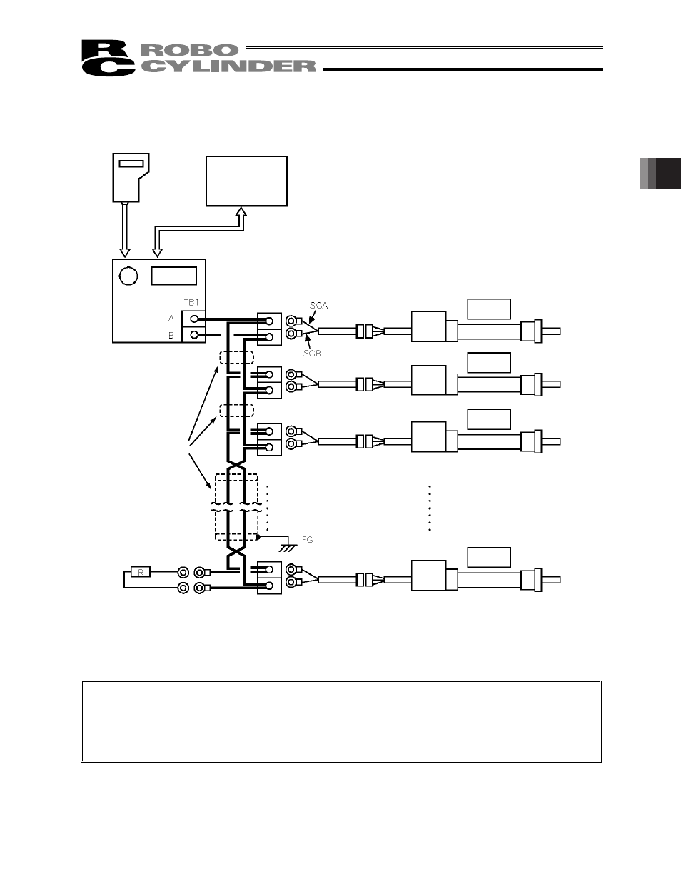
3.2.1 Example of Connecting Multiple Axes Using Link Cables
(Note 1) If the total length of the communication cable is 10 m or longer and you experience communication
errors, connect a terminal resistor to the last axis.
(Note 2) If the actuators use different power supplies, align 0 [V] on all power supplies.
(Note 3) Connect the shielded wire of each axis to FG.
(Note 4) If the overall length of link cable exceeds 30 m, use wire of 22AWG or larger size.
Teaching pendant
PC
Relay terminal
block
Actuator 1
Actuator 2
Actuator 3
One-pair
shielded cable
Terminal resistor
1/2W, 220 :
SIO converter
Actuator 16
See also other documents in the category IAI America Hardware:
- ERC2 (138 pages)
- ERC3 (438 pages)
- ERC (153 pages)
- RCA-E (53 pages)
- RCA-P (42 pages)
- RCB-101-MW (38 pages)
- RCP2-C (178 pages)
- RCS-E (102 pages)
- RCA-A4R (72 pages)
- RCA-RA3C (114 pages)
- RCA-SRA4R (56 pages)
- RCA2-RA2AC (100 pages)
- RCA2-SA2AC (92 pages)
- RCA2-TA4C (134 pages)
- RCD-RA1D (40 pages)
- RCP2-BA6 (72 pages)
- RCP2-GRSS (130 pages)
- RCP2-HS8C (126 pages)
- RCP2-RA2C (120 pages)
- RCP2-RTBS (80 pages)
- RCP2W-SA16C (46 pages)
- RCP3-RA2AC (60 pages)
- RCP4-RA5C (82 pages)
- RCP4-SA5C (94 pages)
- RCP4W (96 pages)
- RCS2-F5D (142 pages)
- RCS2-GR8 (46 pages)
- RCS2-RN5N (80 pages)
- RCS2-RT6 (60 pages)
- RCS2-SA4C (258 pages)
- RCS2-TCA5N (62 pages)
- RCL-SA1L (66 pages)
- RCL-RA1L (56 pages)
- RCLE-GR5L (46 pages)
- IK Series (16 pages)
- FS (84 pages)
- IF (76 pages)
- ISB (114 pages)
- ISDA (126 pages)
- ISDB (116 pages)
- ISPWA (90 pages)
- NS (78 pages)
- ICS(P)A (16 pages)
- RS (46 pages)