W iring – IAI America ERC2 User Manual
Page 57
3. W
iring
34
z
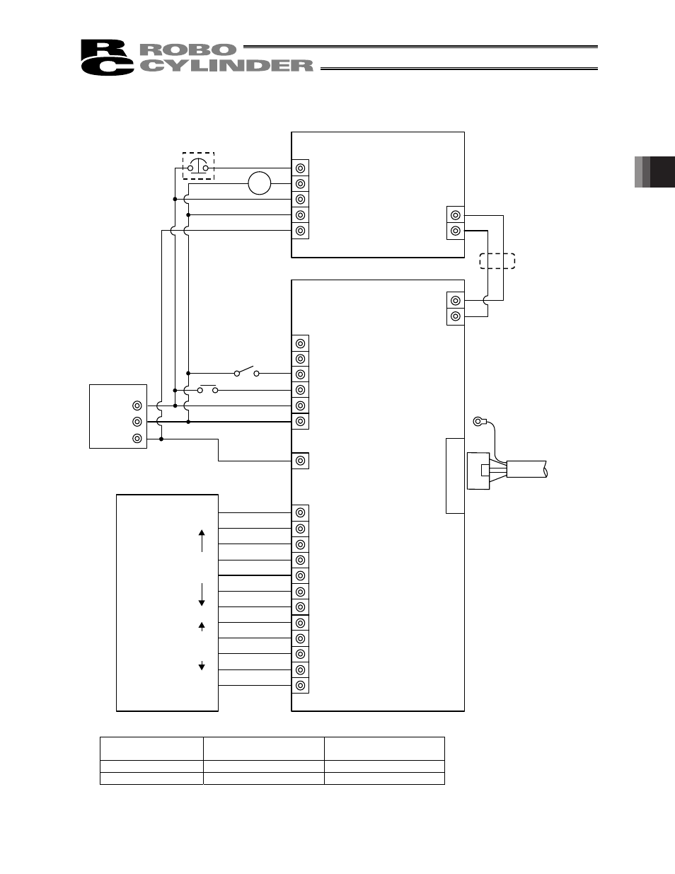
Connection diagram
[1] When the control board is of the NPN specification [sink type]
[1] Insulate the power
supply
[2] Change to PNP
Input common
24 V
0 V
Output common
0 V
24 V
(Note) To release the brake, connect a switch between the TB1-BK terminal and 0 V and turn on the switch.
MC
60 mA Max
TB2
EMG2
EMG1
24V
0V
FG
TB1
A
B
TB2
A
B
TB1
EMS2
EMS1
BK
MP
24V
0V
TB4
FG
TB3
J1
24V
0V
FG
EMG signal
Input power supply
Host system
MC
(Not used)
Twisted pair
Connect to FG
Extension
cable
Motor drive power supply
Control power supply
Contact output for EMG
switch on teaching pendant
Insulated PIO terminal block (RCB-TU-PIO-A/B)
1
2
3
4
5
6
7
8
9
10
11
12
O
ut
pu
t
side
In
pu
t
side
Brake release
switch
Output
common
Input
common
SIO converter (RCB-TU-SIO-A/B)
I/O interface
(Refer to 4.3, “Insulated PIO
Terminal Block.”)
(Note)
Relay
- ERC2 (138 pages)
- ERC3 (438 pages)
- ERC (153 pages)
- RCA-E (53 pages)
- RCA-P (42 pages)
- RCB-101-MW (38 pages)
- RCP2-C (178 pages)
- RCS-E (102 pages)
- RCA-A4R (72 pages)
- RCA-RA3C (114 pages)
- RCA-SRA4R (56 pages)
- RCA2-RA2AC (100 pages)
- RCA2-SA2AC (92 pages)
- RCA2-TA4C (134 pages)
- RCD-RA1D (40 pages)
- RCP2-BA6 (72 pages)
- RCP2-GRSS (130 pages)
- RCP2-HS8C (126 pages)
- RCP2-RA2C (120 pages)
- RCP2-RTBS (80 pages)
- RCP2W-SA16C (46 pages)
- RCP3-RA2AC (60 pages)
- RCP4-RA5C (82 pages)
- RCP4-SA5C (94 pages)
- RCP4W (96 pages)
- RCS2-F5D (142 pages)
- RCS2-GR8 (46 pages)
- RCS2-RN5N (80 pages)
- RCS2-RT6 (60 pages)
- RCS2-SA4C (258 pages)
- RCS2-TCA5N (62 pages)
- RCL-SA1L (66 pages)
- RCL-RA1L (56 pages)
- RCLE-GR5L (46 pages)
- IK Series (16 pages)
- FS (84 pages)
- IF (76 pages)
- ISB (114 pages)
- ISDA (126 pages)
- ISDB (116 pages)
- ISPWA (90 pages)
- NS (78 pages)
- ICS(P)A (16 pages)
- RS (46 pages)