1 overview of the “3 points” mode – IAI America ERC2 User Manual
Page 107
6. Operation in the “3 Points (Air Cylinder)” Mode
84
6. Operation in the “3 Points (Air Cylinder)” Mode
6.1 Overview of the “3 Points” Mode
This mode provides a control method adjusted to that of an air cylinder by assuming that the actuator is used as an air
cylinder.
The key differences between the ERC2 and an air cylinder are summarized below. Perform proper control by referring
to this table.
Item
Air cylinder
ERC2
Drive method Air pressure supplied via
electromagnetic valve
control
Ball screw/timing belt driven by a motor
Target position
setting
Mechanical stopper
(including shock absorber)
Desired coordinates are entered in the [Target position] field of the
position table.
The coordinates can be typed in from the number keys on the PC
keyboard or on the teaching pendant, or set directly by moving the
actuator to the target position.
Target position
detection
An external detection
sensor, such as a reed
switch, is installed.
Determined based on the internal coordinates provided by the position
information from the position detector (encoder).
Accordingly, external detection sensor is not required.
Speed setting Adjusted by a speed
controller.
A desired feed speed is entered in the [Speed] field of the position table
(unit: mm/sec).
Note that the rated speed is automatically set as the initial value.
Acceleration/
deceleration
setting
Determined in accordance
with the load, supplied air
volume, as well as the
performance of the speed
controller and
electromagnetic valve.
A desired acceleration/deceleration is entered in the
[Acceleration/deceleration] field of the position table (unit: 0.01 G).
(Reference) 1 G = Gravitational acceleration
Note that the rated acceleration/deceleration is automatically set as the
initial value.
Since the acceleration/deceleration can be set in fine steps, a gradual
acceleration/deceleration curve can be programmed.
Position check
upon power
ON
Determined by an external
detection sensor, such as
a reed switch.
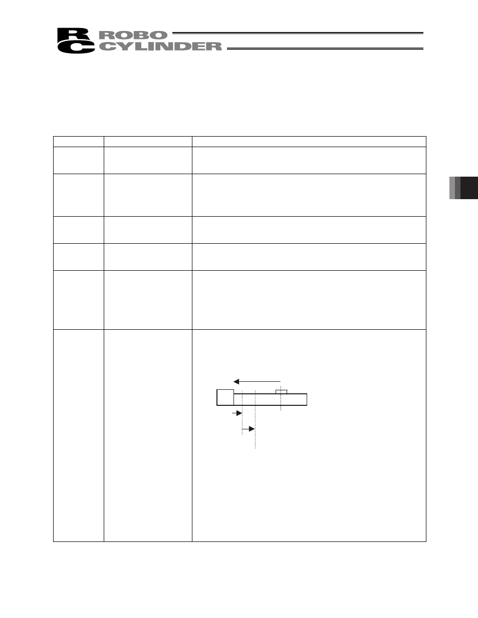
Immediately after the power is turned on, the controller cannot identify the
current position because the mechanical coordinates have been lost.
Therefore, when the first movement command is issued after the power
has been input, the controller will automatically perform home return
before moving the actuator to the target position.
[1] The actuator moves at the home return speed toward the mechanical
end on the motor side.
[2] The actuator hits the mechanical end and turns back, and then stops
temporarily at the home position.
[3] The actuator moves to the target position at the speed specified in
the [Speed] field of the position table.
(Note) Pay attention not to allow any obstacle in the travel path of
the actuator during home return.
Home
position
[1]
[2]
[3]
Target position
Power is turned
on here.