3 speed change during movement – IAI America ERC2 User Manual
Page 101
5. Data Entry
78
(4)
Positioning band was entered with a wrong sign
If the value in the “Positioning band” field of the position table is entered with a wrong sign, the position will deviate by
twice the positioning band, as shown below. Accordingly, pay due caution to the entry in this field.
5.2.3 Speed Change during Movement
Speed control involving multiple speed levels is possible in a single operation. The actuator speed can be decreased
or increased at a certain point during movement.
However, the position at which to implement each speed change must be set.
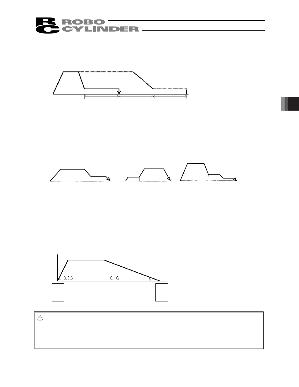
5.2.4 Operation at Different Acceleration and Deceleration Settings
If the work part is a CCD camera or other precision instrument, a more gradual deceleration curve is needed when the
actuator stops.
To support these applications, the position table has separate fields for “Acceleration” and “Deceleration.”
You can set the acceleration and deceleration differently, such as setting 0.3 G (rated value) in “Acceleration” and 0.1
G in “Deceleration.”
Caution: Basically, you should set the acceleration/deceleration within the rated range specified in the
catalog.
The input range is greater than the rated range in the catalog, in order to accommodate situations
where you want to “shorten the tact time when the transferring mass is much smaller than the rated
loading capacity.” If the actuator is to be operated in this condition, however, its service life may be
affected. Contact IAI beforehand for consultation.
Position 1
Position 2 Position 1
Position 2
Position 1 Position 2 Position 3
Speed
Moving
distance
Positioning
band
Positioning
band
Positioning
band
Actual position reached
(the work part is
missed)
Target
position
Time
Speed
Acceleration
Deceleration
S
ta
rti
ng
po
si
tio
n
Ta
rg
et
po
si
tio
n