10 zone signal – IAI America ERC2 User Manual
Page 136
7.
O
pe
ra
tio
n
in
th
e
“8
P
oi
nt
s”
a
nd
“
16
P
oi
nt
s”
M
od
es
<
Pr
ac
tic
al
O
pe
ra
tio
n>
113
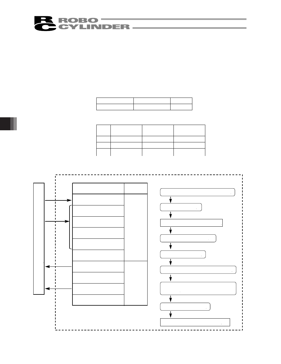
7.10 Zone Signal
How the boundaries are set varies depending on the PIO pattern.
x
If fixed boundaries are applied to all operations, set them using parameters. (PIO pattern = 0 or 2).
x
To set different boundaries for each position number to support multiple loads, set respective settings in the
position table. (PIO pattern = 3)
Example of use in operation) Output a zone signal in a range of 40 to 120 mm while the actuator is moving from the
home to the 150-mm position (position 1).
Method) x PIO pattern = 0 or 2
Use the parameters “Zone boundary+” and “Zone boundary–” to set the zone in
which the zone signal is output, as shown below:
Parameter No. 1
Zone boundary+ 120 (mm)
Parameter No. 2
Zone boundary–
40 (mm)
x
PIO pattern = 3
Use the “Zone+” and “Zone-” fields of the position table to set the zone in which
the zone signal is output, as shown below:
No.
Position
[mm]
Zone+
[mm]
Zone-
[mm]
0
*
*
*
1
150.00
120.00
40.00
x
x
x
ERC2 controller
P
L
C
[4] [2]
[1]
[7] [3]
[6] [5]
Signal name
Start
Command position 1
Command position 2
Command position 4
Command position 8
*Pause
Position complete
Home return completion
Zone
*Alarm
Category
Input
Output
PIO
Selection/entry of command position No. 1
Start input ON
Position complete output OFF
Start input OFF
Movement to position 1 completes.
Position complete output ON
Movement to position 1 starts.
Actuator enters the zone. Zone output ON
Actuator exits the zone. Zone output
OFF
Reference flow
[1]
[2]
[3]
[4]
[5]
[6]
[7]