1 explanation of i/o signals – IAI America ERC2 User Manual
Page 64
0
3. W
iring
41
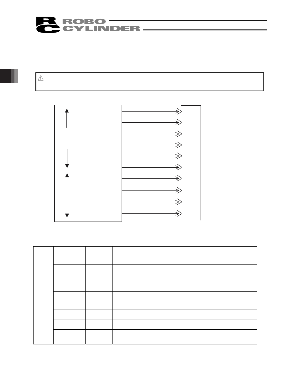
3.6 I/O Signals for PIO Pattern 1 [3 Points] (Air Cylinder)
The following description assumes that the actuator is used in place of an air cylinder.
The number of positioning points is limited to three, but a direct command input and a position complete output are
provided separately for the target position in line with the conventional practice of air cylinder control.
Caution: The factory setting is “8 points,” so set parameter No. 25 to “1.” The pause signal can be disabled in
parameter No. 15.
(Note) *STP and *ALM are always ON.
3.6.1 Explanation of I/O Signals
Category Signal name
Signal
abbreviation
Function overview
Rear end move
ST0
The actuator starts moving to the rear end at the rise edge of the signal.
Front end move
ST1
The actuator starts moving to the front end at the rise edge of the signal.
Intermediate
point move
ST2
The actuator starts moving to the intermediate point at the rise edge of the
signal.
*Pause
*STP
ON: The actuator can be moved, OFF: The actuator decelerates to a stop
Input
Alarm reset
RES
This signal resets the alarm output signal.
Rear end
complete
PE0
The signal turns ON when the actuator completes moving to the rear end.
Front end
complete
PE1
The signal turns ON when the actuator completes moving to the front end.
Intermediate
point complete
PE2
The signal turns ON when the actuator completes moving to the intermediate
point.
Output
*Alarm
*ALM
This signal remains ON while the controller is operating properly, and turns
OFF when an alarm generates.
(Note) The signal remains ON while the motor drive power is cut off.
Orange (Red 2)
Orange (Black 2)
*Light blue (Red 2)
*Light blue (Black 2)
White (Red 2)
White (Black 2)
Yellow (Red 2)
Yellow (Black 2)
Pink (Red 2)
Pink (Black 2)
6A
ST0
6B
ST1
7A
ST2
7B
8A
RES
8B
*STP
9A
PE0
9B
PE1
10A
PE2
10B
*ALM
Host system
ERC2 actuator end
CN1
(Signal abbreviation)
Output
side
Input
side
Rear end move
Front end move
Intermediate point
move
Alarm reset
Pause
Rear end complete
Front end complete
Intermediate point
complete
Alarm
* Robot cable
Gray (Red 2)
Gray (Black 2)