6 push & hold mode – IAI America ERC2 User Manual
Page 127
7. O
pe
ra
tio
n i
n t
he
“8
P
oin
ts
” a
nd
“1
6 P
oin
ts
” M
od
es
<
Pr
ac
tic
al O
pe
ra
tio
n>
104
7.6 Push & Hold Mode
First, cause the position complete signal to turn ON by referring to 7.1, “How to Start.”
Example of use in operation) The actuator is caused to move back and forth in the push & hold mode and
positioning mode. The position 280 mm from the home is set as position 1, and the
position 40 mm from the home is set as position 2.
Movement to position 1 is performed in the push & hold mode (the actuator is caused
to contact the work part and push it in the counter-motor direction). The maximum
push amount at position 1 is set as 15 mm, and the current-limiting value during the
push & hold operation by the motor is set as 50%. Movement to position 2 is
performed in the positioning mode. The travel speed to position 1 is set as 200
mm/sec, and that to position 2 is set as 100 mm/sec.
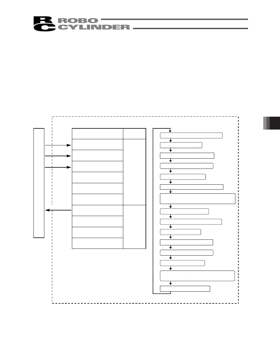
ERC2 controller
Signal name
Start
Command position 1
Command position 2
Command position 4
Command position 8
*Pause
Position complete
Home return completion
Zone
*Alarm
P
L
C
PIO
Category
Input
Output
Reference flow
Select/enter command position 1.
Start input ON
Movement to position 1 starts.
Position complete output OFF
Start input OFF
Position complete output ON
Select/enter command position 2.
Start input ON
Movement to position 2 starts.
Position complete output OFF
Start input OFF
Movement to position 2 completes.
Move at slow speed after passing position 1.
Work part is pushed. Stepper motor
current rises to the current-limiting value.
Position complete output turns ON 0.1 mm
before position 2.
[1]
[2]
[3]
[4]
[5]
[6]
[7]
[8]
[9]
[10]
[9] [7] [4] [2]
[1]
[6]
[10] [8] [5] [3]