W iring – IAI America ERC2 User Manual
Page 46
3. W
iring
23
z
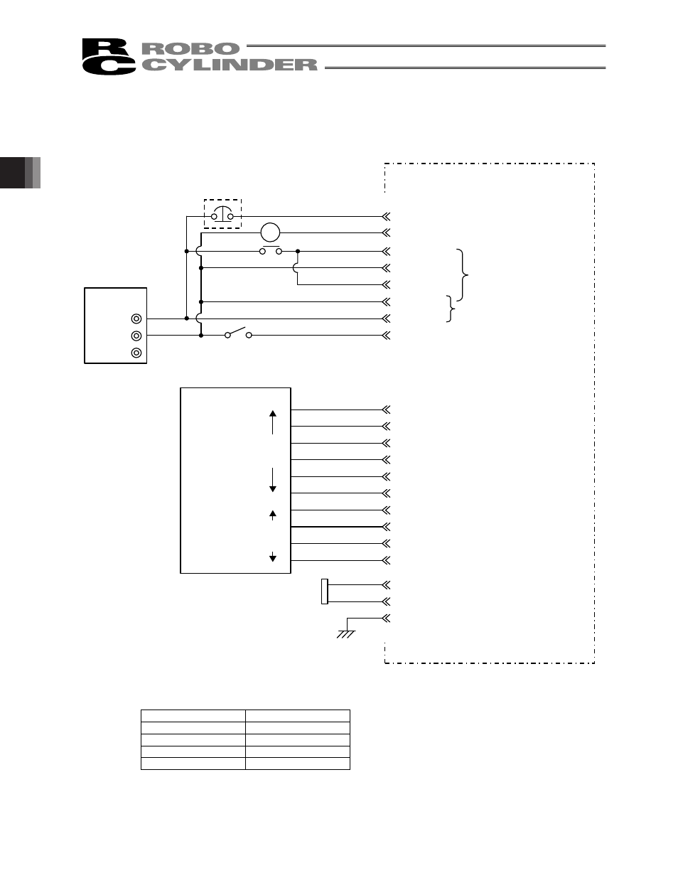
Connection diagram
[1] When the control board is of the NPN specification [sink type]
* In the case of a robot cable, the wire colors change as follows.
Wire color
Pin number
Gray (Red 1)
2A
Gray (Black 1)
2B
Gray (Red 2)
7A
Gray (Black 2)
7B
(Note) To release the brake, connect a switch between BKR and 0 V and turn on the switch.
MC
60 mA max
2A
EMS1
2B
EMS2
4A
MPI
4B
GND
5A
MPI
5B
GND
3A
24V
3B
BKR
24V
0V
FG
Orange (Red 2)
Orange (Black 2)
*Light blue (Red 2)
*Light blue (Black 2)
White (Red 2)
White (Black 2)
Yellow (Red 2)
Yellow (Black 2)
Pink (Red 2)
Pink (Black 2)
6A
6B
7A
7B
8A
8B
9A
9B
10A
10B
Orange (Red 1)
Orange (Black 1)
1A
SGA
Serial communication
1B
SGB
Drain wire
CN2
FG
EMG signal
Input power supply
(2 A or more)
Brake release
switch
ERC2 actuator
Contact output for EMG
switch on teaching pendant
Motor drive power supply
Control power supply
OFF when the brake is
controlled by the controller, or
ON when the brake is released
(Applicable to an actuator with
brake)
Host system
O
ut
pu
t
side
In
pu
t
side
(Not used)
CN1
*Light blue (Red 1)
*Light blue (Black 1)
Yellow (Red 1)
Yellow (Black 1)
Pink (Red 1)
Pink (Black 1)
White (Red 1)
White (Black 1)
I/O interface
(Refer to the I/O connections for each
PIO pattern)
(Note)
Relay