E zxxx, Query firmware version (verbose) – Extron Electronics MTPX Plus 6400 Series User Guide User Manual
Page 87
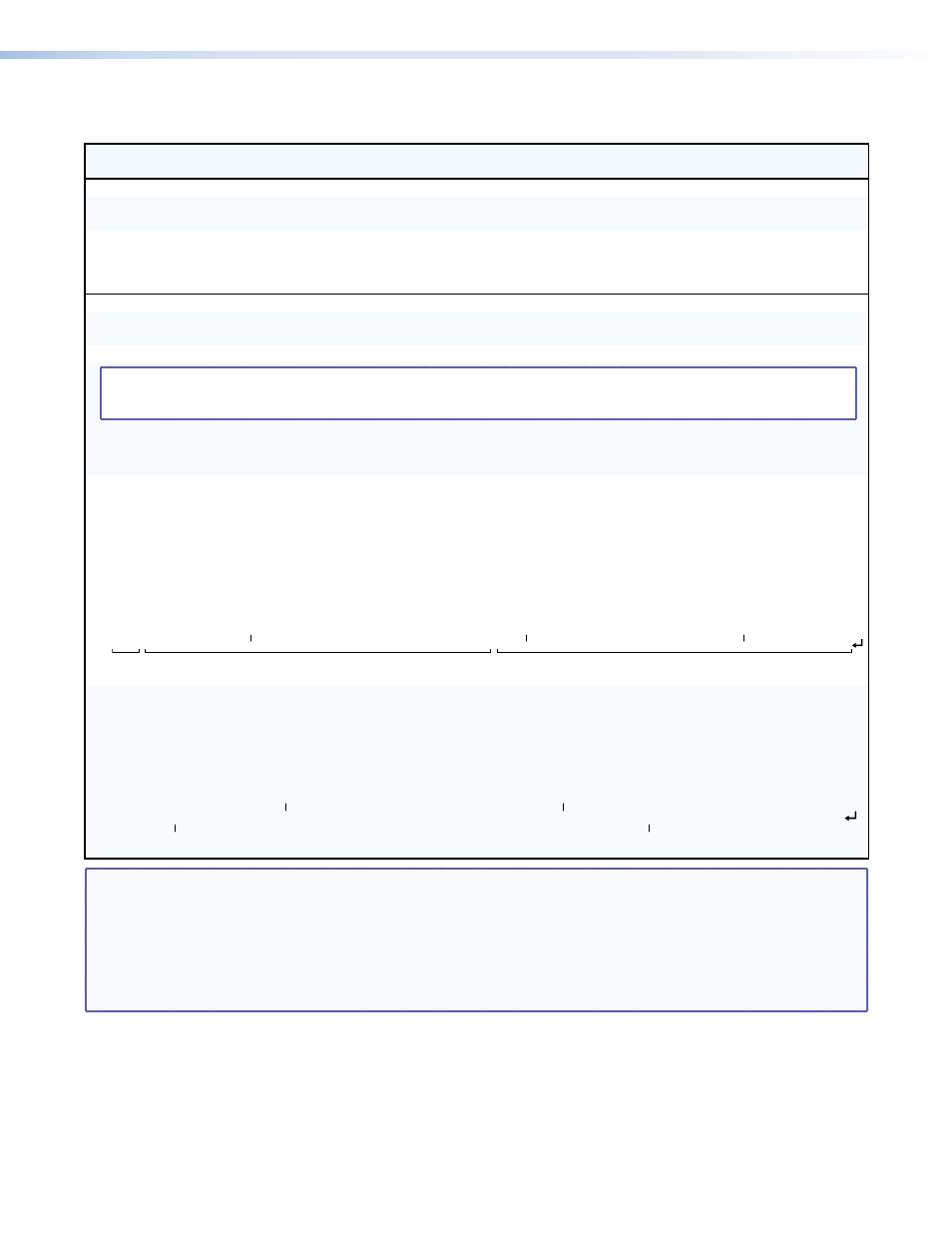
Command/Response Table for SIS Commands (continued)
Command
ASCII Command
(Host to Unit)
Response
(Unit to Host)
Additional Description
Resets (continued)
Reset whole switcher
E
ZXXX
}
Zpx
]
Clear all ties and presets, reset all all audio
gains to 0 dB, and reset volume to 100%.
Absolute reset
E
ZQQQ
}
Zpq
]
Similar to Reset whole switcher, plus
clear all UART ports, reset the IP address to
192.168.254.254, and reset the subnet mask
to 255.255.000.000.
Information requests
Information request
I
V
X2*
X
X2(
•A
X2*
X
X2(]
V
X2*
X
X2(
shows the video matrix size.
A
X2*
X
X2(
shows the audio matrix size.
Request part number
N
X3)]
See “
.”
NOTE: There are up to three separate sets of firmware on which the switcher can report: the controller firmware, which is the overall
control firmware; the Ethernet protocol firmware, which handles the Ethernet interface; and the latest optional controller
firmware update, which is available at
www.extron.com
.
Query firmware version
Q
X3!]
Example:
Q
1.23
]
The factory-installed controller firmware
version is 1.23 (sample value only).
Query controller firmware
version (verbose)
ØQ
X3!
-
X3@
-
X3@]
Provide a detailed status of the Ethernet protocol
firmware, the controller firmware, and any
firmware upgrade. An asterisk (*) marks the
firmware that is running. A caret (^) marks
that the firmware has a bad checksum or an
invalid load. ?.?? marks that firmware is not
loaded.
Response description:
Ethernet protocol firmware version-controller firmware version-updated firmware version
]
Example:
Øq
Ethernet
protocol
firmware
Description
MTPX firmware version
Updated firmware version
* indicates the version running
Upload date and time
1.00-1.23(1.81-MTPX 64 Series -Wed, 05 Jan 2011 00:00:00 GMT)-1.13*(1.81-MTPX 64 Series -Wed, 12 Jan 2011 16:39:21 GMT)
Request system status
S
X3#
•
X3#
•
X3#
•
X3#
•
X3#
•
X3#
•
X3$
•
X3%
•
X3%
•
X3#
•
X3#
•
X3#
•
X3$
•
X3%
•
X3%
•
X3%
•
X3%
•
X3%
•
X3^
•
X3^
•
X3^
•
X3^]
Response description:
+5V•–5V•+12V•–12V•+2.5V•–2.5V•Temp 1•Fan 1 RPM•Fan 2 RPM•+9V•–9V•+3.3V•Temp 2•Fan 3 RPM•Fan 4 RPM•Fan 5 RPM•
Fan 6 RPM•Fan 7 RPM•Pri 1 PS status•Red 1 PS status•Pri 2 PS status•Red 2 PS status
]
Example:
S
- 2.5 V power system at 2.49 V
Internal temperature at sensor 2 is 77.0° F
Fan 4 rotating at 2,766 RPM
12.00 V power system at 12.02 V
5.06•-5.03•12.02•-11.90•2.50•-2.49•+77.00•02766•02812•8.94•-8.90•3.31•+77.00•02766•02766•02721•02812•02766•1•1•1•1
NOTE:
X2*
= Number of inputs
48 or 64
X2(
= Number of outputs
32, 48, or 64
X3)
= Part number
See “
”
X3!
= Firmware version number to second decimal place (n.nn)
X3@
= Verbose firmware version-description-upload date and time (see above).
X3#
= Voltage
Voltage, polarity (positive or negative) and magnitude
X3$
= Internal temperature
Degrees Fahrenheit
X3%
= Fan speed
RPM
X3^
= Power supply status
1 = Ok
0 = Out of tolerance or failed
MTPX Plus 6400 Series Matrix Switchers • Programming Guide
81