Extron Electronics MTPX Plus 6400 Series User Guide User Manual
Page 20
NOTES: Enhanced Skew-free A/V cable is not recommended for Ethernet/LAN
applications. This cable is specially designed for compatibility with the Extron
twisted pair products that are wired using the TIA/EIA 568A standard.
• The green, brown, and blue pairs of this cable have virtually identical
lengths and should be used to transmit the RGB signals.
• The orange pair of this cable has a different length and should not be
used to transmit the RGB signals.
b
Local Inputs (VGA) connectors — Connect analog computer-video
RGB
(RGB) sources to these 15-pin HD female connectors.
NOTES: • The video that is input on this connector, when it is tied to a TP output,
is converted to same type of the proprietary TP signal that is output by
the MTP 15HD transmitters. This allows you to eliminate some of the
transmitters in a system.
• When either the input or output of a tie is local (VGA), Extron
recommends that the MTP output or input be connected by a minimum
of 25 feet (7.5 m) of TP cable to prevent overpeaking.
• The matrix switchers can also input and switch HD component video,
component video, S-video, or composite video by using the appropriate
adapters and the pins show in figure 5. No configuration of the switcher
is required for component or other non-RGB video formats.
Pin
1
2
Video
3
6
7
Video return
Video 2*
Video 2 return*
Video 3*
Video 3 return*
8
4-5
Signal
R-Y
Y
B-Y
R-Y return
Y return
B-Y return
Signal
Component
S-video
Composite
Signal
Chroma (C)
Luma (Y)
Chroma return
Luma return
9-15
5
1
15
11
6
10
Female
* You can input and output additional, genlocked, composite video pins 1, 3, 6, and 8.
NOTE: Input only sync signals, no video signals, on the sync pins (13 and 14).
Figure 5.
Other Video Formats on a VGA Connector
c
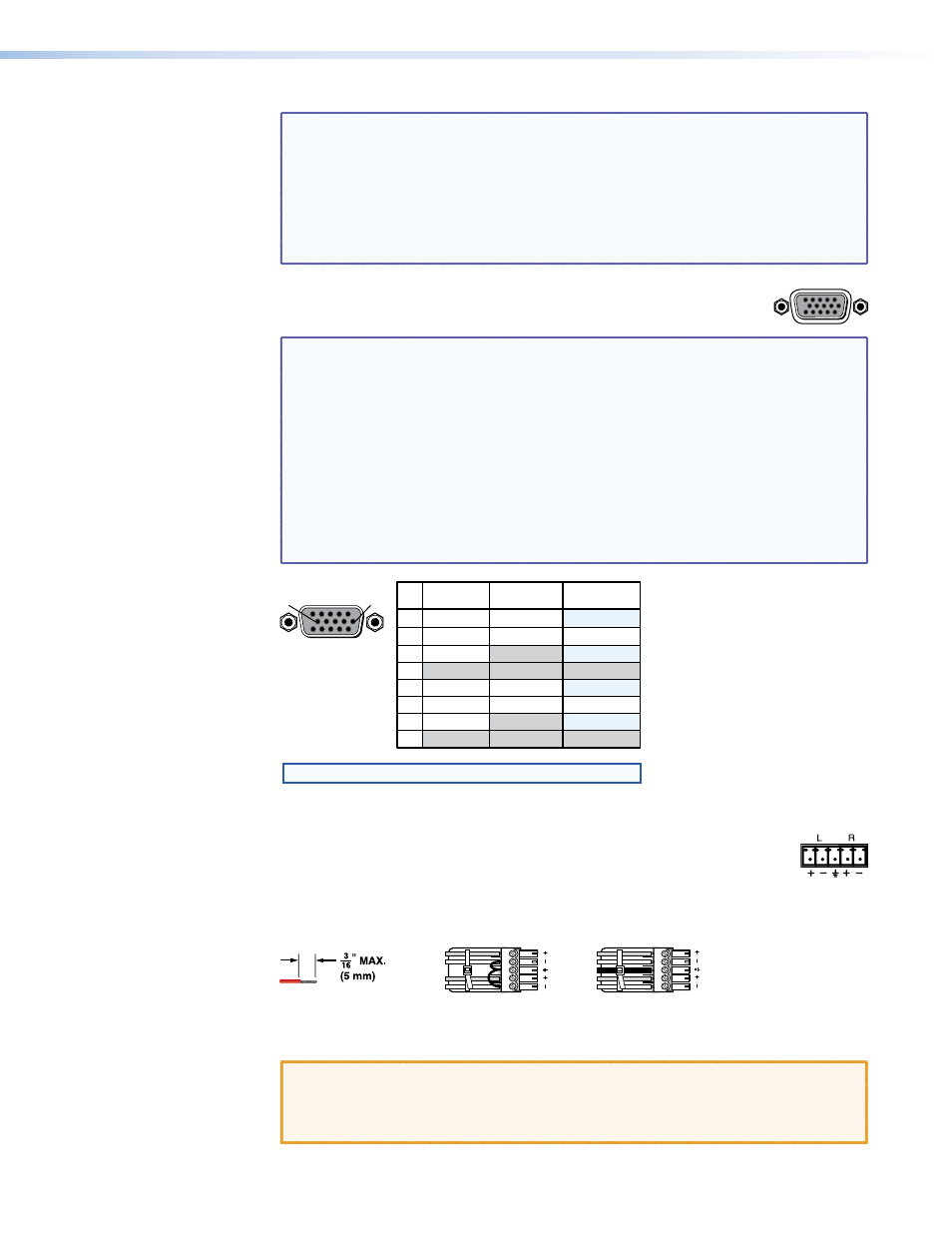
Audio Inputs (local audio) connectors — Connect balanced or
unbalanced stereo audio inputs to these 3.5 mm, 5-pole captive screw
connectors. Connectors are included with each switcher, but you must supply
the audio cable. See figure 6 to wire a connector for the appropriate input
type. Use the supplied tie-wrap to strap the audio cable to the extended tail of the
connector.
LR
Unbalanced Stereo Input
Balanced Stereo Input
Ring
Sleeve (s)
Tip
Sleeve
Tip
Sleeve
Tip
Tip
Ring
Do not tin the wires!
Figure 6.
Captive Screw Connector Wiring for Audio Inputs
CAUTION: The captive screw audio connector can easily be inadvertently plugged
partially into one receptacle and partially into an adjacent receptacle.
This misconnection could damage the audio circuits. Ensure that the
connector is plugged fully and only into the desired input or output.
MTPX Plus 6400 Series Matrix Switchers • Installation
14