Removing and installing a power supply module, Removing a power supply module, Installing a power supply module – Extron Electronics MTPX Plus 6400 Series User Guide User Manual
Page 148: Removing and installing, A power supply module, Maintenance and modifications, Maintenance and, Modifications, Figure 78. power supply replacement, Fan assembl y
Removing and Installing a Power Supply Module
Each power supply module has a 2-color LED that indicates the status of the power supply
outputs. If the LED is lit green, the power supply is operating normally. If the LED is lit red,
the supply has failed and should be replaced at the earliest opportunity.
Removing a Power Supply Module
NOTE: The power supply modules are hot-swappable. Any power supply can be
removed without powering down the switcher.
Remove a power supply module as follows:
1.
Rotate the left and right knurled knobs to completely loosen the screws.
2.
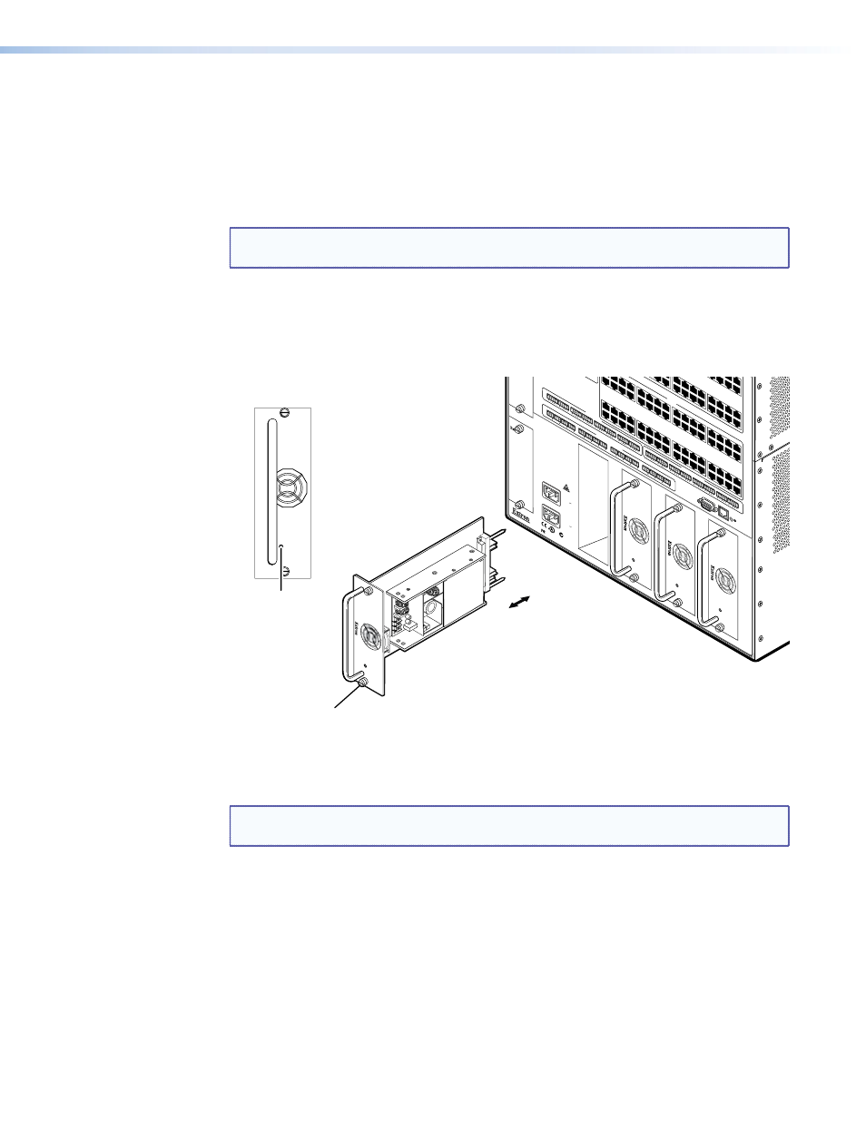
Gently pull on the handle to loosen the power supply from the backplane (see figure 78).
3.
Slide the power supply out of the chassis.
ANAHEIM,
CA
RESET
RS232/RS422
REMO
TE
LAN
ACT
LINK
100-240V
50/60Hz
6.4A MAX.
100-240V
50/60Hz
1.2A MAX.
REDUND
ANT
PRIMAR
Y
LISTED
1T23
US
®
N15779
FAN ASSEMBL
Y
29
30
31
32
RS-232 OUTPUT INSER
TION
AUDIO INPUTS
L
R
1
L
R
2
L
R
3
L
R
4
L
R
5
L
R
6
Tx
Rx
1
Tx
Rx
2
Tx
Rx
3
Tx
Rx
4
Tx
Rx
5
Tx
Rx
6
Tx
Rx
7
Tx
Rx
8
42
43
44
45
46
47
48
54
55
56
57
58
59
60
61
62
63
64
L
R
7
L
R
8
MONO AUDIO OUTPUTS
L
R
1
L
R
2
L
R
3
L
R
4
L
R
5
L
R
6
L
R
7
L
R
8
4
5
6
7
8
9
10
11
12
13
14
15
16
17
18
19
20
21
22
23
24
25
26
27
28
29
30
31
32
OUTPUTS
33
34
35
36
37
38
39
40
41
42
43
44
45
46
47
48
49
50
51
52
53
54
55
56
57
58
59
60
61
62
63
64
Tx
Rx
9
Tx
Rx
10
Tx
Rx
11
Tx
Rx
12
Tx
Rx
13
Tx
Rx
14
Tx
Rx
15
Tx
Rx
16
PRIMAR
Y PO
WER SUPPL
Y 1
PRIMAR
Y PO
WER SUPPL
Y 2
REDUND
ANT PO
WER SUPPL
Y 1
REDUND
ANT PO
WER SUPPL
Y 2
Power
LED
Align with Plastic Guides
Knurled Knobs
Figure 78.
Power Supply Replacement
Installing a Power Supply Module
NOTE: The power supply modules are hot-swappable. You do not need to power down
the switcher to install a power supply.
Install a power supply module as follows:
1.
Orient the power supply module to be installed with the LED down.
2.
Align the flanges on the power supply module with the top and bottom power supply
guides (see figure 78).
3.
Gently slide the power supply module into the enclosure until the power supply meets
resistance.
4.
Gently seat the power supply in the backplane.
5.
Use a screwdriver to tighten the top and bottom screws to lock the power supply in
place.
MTPX Plus 6400 Series Matrix Switchers • Maintenance and Modifications 142