Rs-232 output inserts – Extron Electronics MTPX Plus 6400 Series User Guide User Manual
Page 21
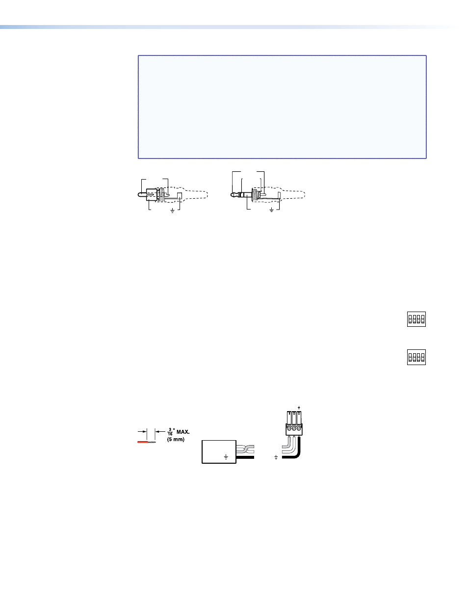
NOTES: • The length of exposed wires is critical. The ideal length is 3/16 inch (5 mm).
z
z
If the stripped section of wire is longer than 3/16 inch, the exposed
wires may touch, causing a short circuit.
z
z
If the stripped section of wire is shorter than 3/16 inch, wires can be
easily pulled out even if tightly fastened by the captive screws.
• Figure 7 identifies the tip, ring, and sleeve. A mono audio connector
consists of the tip and sleeve. A stereo audio connector consists of the
tip, ring and sleeve. The tip, ring, and sleeve wires are also shown on the
captive screw audio connector diagrams (see
on the previous
page and
Tip (+)
Sleeve ( )
Sleeve ( )
Ring (-)
Tip (+)
RCA Connector
3.5 mm Stereo Plug Connector
(balanced)
Figure 7.
Typical Audio Connectors
The audio level for each input can be individually set via the front panel or Ethernet or
RS-232 control to ensure that the level on the output does not vary from input to input
(see the “
” section, page 76;
” section, page 105; and the “
” section,
page 136).
d
Input Select switches — For inputs 1 through 8, set these DIP switches to
RJ-45
INPUT
SELECT
LOCAL
1 2 3 4
RJ-45
LOCAL
5 6 7 8
the Local (up) position to select the local (RGB video and audio) input. Set the
DIP switches to the RJ-45 (down) position to select the MTP input.
RS-232 Output Inserts
e
RS-232 Output Insert connectors — For bidirectional RS-232 data that is
routed to a specific (unswitchable) TP output, connect a serial device to one
of these 3.5 mm, 3-pole captive screw connectors. Figure 8 shows how to wire the
connectors.
Receive (Rx)
Transmit (Tx)
Ground ( )
Bidirectional
RS-232
Device
Ground ( )
Receive (Rx)
Transmit (Tx)
Rx
Tx
Do not tin the wires!
Figure 8.
RS-232 Output Insert Wiring
For the RS-232 Output Insert to be available on the TP output, the insert must be
enabled via an SIS command, the Windows-based control program, or an MTPX
Plus HTML page (see the “
” section, page 106; and the “
Each RS-232 output insertion is dedicated to the output with that number; for example,
RS-232 Output Insert 1 is always routed to the Output 1 TP connector (when enabled
as described in the note above), RS-232 Output Insert 2 is routed to the Output 2 TP
connector, and so on.
MTPX Plus 6400 Series Matrix Switchers • Installation
15