Signal outputs, Figure 9 – Extron Electronics MTPX Plus 6400 Series User Guide User Manual
Page 22
NOTES: • When an RS-232 output insert is enabled, any content on the
audio/RS-232 wire pair for the TP input tied to that output is disabled.
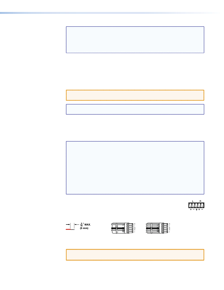
• The length of exposed wires is critical. The ideal length is 3/16 inch
(5 mm) (see the audio input connector
for more information).
• The switch time for the RS-232 output insert is 50 ms.
Signal Outputs
f
Outputs (TP) connectors — Connect the TP inputs of compatible MTP or VTR receivers
to these RJ-45 female connectors.
See the Inputs connector,
, in the “Signal inputs” section, for detailed pin
assignments for the RJ-45 connectors.
CAUTION: Do not connect this device to a computer data or telecommunications
network.
NOTE: For best results, use a minimum cable length of at least 25 feet (7.5 m)
between the TP output connector and the receiver
g
Local Outputs (VGA) connectors — Connect up to four RGBHV video displays to
these 15-pin HD female connectors for each output.
These outputs are always outputs 1 through 4, with the same inputs tied to them as to
TP outputs 1 through 4.
NOTES: • The video that is output on these connectors is converted from the tied
proprietary TP input signal or the local (VGA) input. This feature allows
you duplicates of outputs 1 through 4 while eliminating the need for
extra receivers.
• When either the output or input of a tie is local (VGA), Extron
recommends that the MTP input or output be connected by a minimum
of 25 feet (7.5 m) of TP cable to prevent overpeaking.
• The matrix switchers can also input and switch HD component video,
component video, S-video, or composite video by using the appropriate
adapters and the pins shown in
on page 14. No configuration of
the switcher is required for component or other non-RGB video formats.
h
Mono Audio (local audio) outputs — Connect audio devices, such as an
audio amplifier or powered speakers, to these four or eight 3.5 mm, 5-pole
captive screw connectors. These connectors output the selected unamplified,
mono line level audio. See figure 9 to wire an output connector. Use the
supplied tie-wrap to strap the audio cable to the extended tail of the connector.
Ring
Sleeve(s)
Tip
Tip
Ring
Sleeve(s)
Tip
Tip
Unbalanced Stereo Output
Balanced Stereo Output
NO GROUND HERE.
NO GROUND HERE.
LR
Do not tin the wires!
Figure 9.
Captive Screw Connector Wiring for Stereo Audio Output
CAUTION: For unbalanced audio, connect the sleeves to the ground contact.
DO NOT connect the sleeves to the negative (-) contacts.
MTPX Plus 6400 Series Matrix Switchers • Installation
16