Extron Electronics MTPX Plus 6400 Series User Guide User Manual
Page 86
Command/Response Table for SIS Commands (continued)
Command
ASCII Command
(Host to Unit)
Response
(Unit to Host)
Additional Description
View ties, gain, volume, mutes, and presets (continued)
View audio global preset
configuration
EX2@
*
X@
*2VC
}
X!
n
•
X!
n+1
•...•
X!
n+15
•Aud
]
Show the audio configuration for preset
X2@
.
Show the input tied to 16 sequential outputs,
starting from output
X@
. n is the starting
output number.
Command description:
preset # (
X2@
)*starting output # (
X@
)*2 (= audio)VC
Response description:
Input # (
X!
) tied to
X@
•
X!
tied to
X@
+1•
X!
tied to
X@
+2• ... •
X!
tied to
X@
+15•Aud
]
Example:
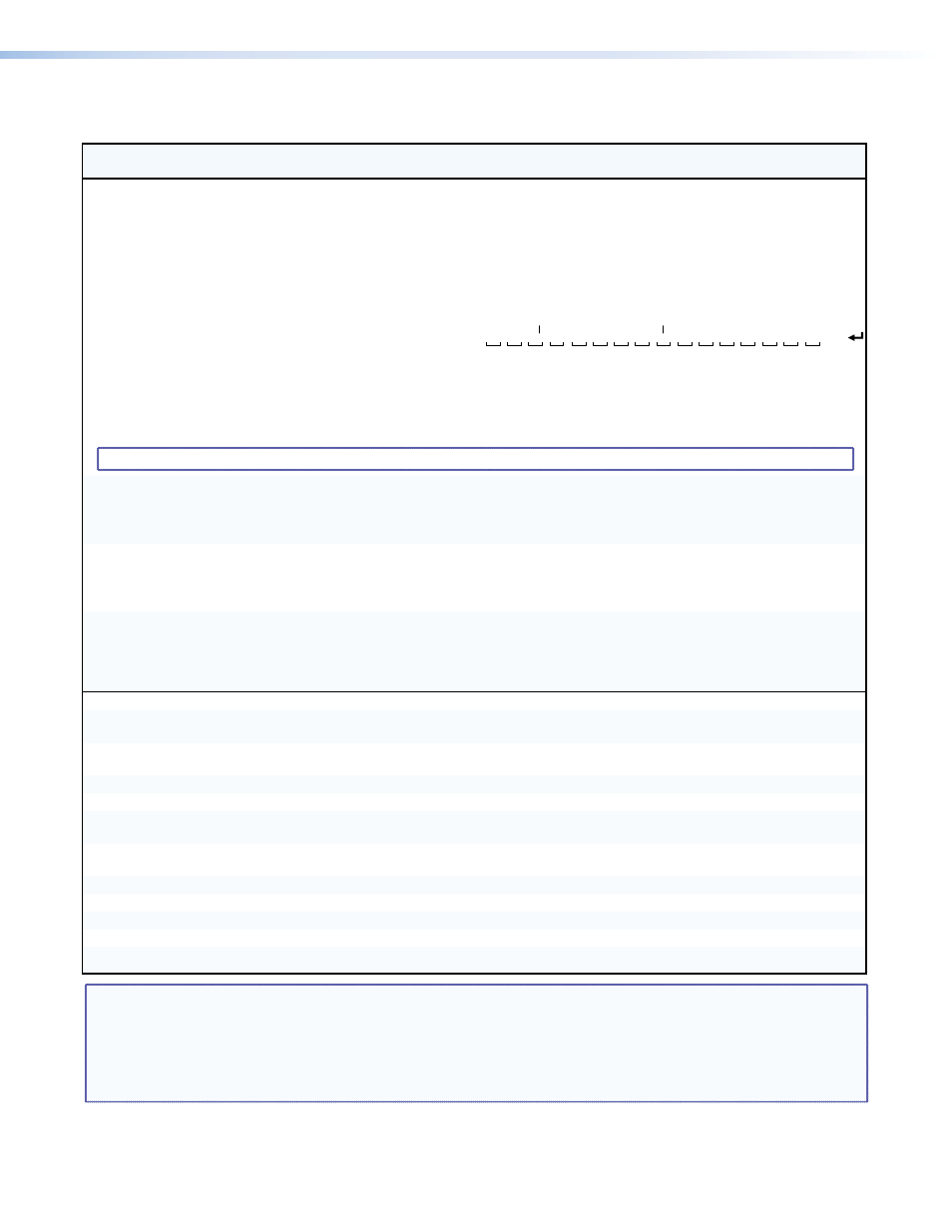
(64 x 32 matrix)
E
15*17*2VC
}
17
Output:
Response = tied input:
input 1 tied to output 19
18 19 20 21 22 23 24 25 26 27 28 29 30 31 32
no tied input
Ш1•Ш1•Ш1•Ш1•Ш2•12•12•ШШ•ШШ•ШШ•ШШ•ШШ•Ш1•Ш8•15•16•Aud
Each position shown in the response is an output: left = starting output (17), right = starting output +15 (32).
The number in each position is the input tied to that output.
In this example, preset 15, audio input 1 is tied to outputs 17, 18, 19, 20, and 29; input 2 is tied to output 21;
input 12 is tied to outputs 22 and 23; input 8 is tied to output 30; input 15 is tied to output 31; and input 16 is
tied to output 32. No input is tied to output 24, 25, 26, 27, and 28.
NOTE:
EX2@
*1*2VC
}
where
X2@
= 0 returns the current audeo configuration of the switcher.
View video room preset
configuration
EX2$
*
X2@
*1*1VC
}
X!
n
•
X!
n+1
•...•
X!
n+15
•Vid
]
Show the video configuration for room
X2$
,
preset
X2@
. Show the input tied to up to 16
outputs assigned to room
X2$
.
Command description:
room # (
X2$
)*preset # (
X2@
)*starting output # (
X@
)*1 (= video)VC
Response description:
input # (
X!
) tied to
X@
•
X!
tied to
X@
+1•
X!
tied to
X@
+2• ... •
X!
tied to
X@
+15•Vid
]
View audio room preset
configuration
EX2$
*
X2@
*1*2VC
}
X!
n
•
X!
n+1
•...•
X!
n+15
•Aud
]
Show audio configuration for room
X2$
, preset
X2@
. Show the input tied to up to 16 outputs
assigned to room
X2$
.
Command description:
room # (
X2$
)*preset # (
X2@
)*starting output # (
X@
)*2 (= audio)VC
Response description:
Input # (
X!
) tied to
X@
•
X!
tied to
X@
+1•
X!
tied to
X@
+2• ... •
X!
tied to
X@
+15•Aud
]
View Input Select DIP
switch positions and level
and peaking status
E
Stat
}
X2&
1
X2&
2
...
X2&
8
*
X*
]
Each
X2&
is the switch position for that rear
panel Input Select DIP switch from 1 to 8.
X*
indicates whether the input level and
peaking is within the pre-determined
threshold for the input tied to output 1 only.
Resets
Reset all input level and
peaking adjustments
E
ZT
}
Zpt
]
Clear all level and peaking adjustments to
their default (0) values.
Reset all input and output
skew adjustments
E
ZK
}
Zpk
]
Clear all input and output skew values to 0 ns.
Reset global presets
E
ZG
}
Zpg
]
Clear all global presets and their names.
Reset one global preset
EX2@
ZG
}
Zpg
X2@]
Clear global preset
X2@
.
Reset audio input levels
E
ZA
}
Zpa
]
Reset all audio input levels
(gain and attenuation) to 0 dB.
Reset audio output levels
E
ZV
}
Zpv
]
Reset all audio output levels (volume) to 100%
(no attenuation).
Reset all mutes
E
ZZ
}
Zpz
]
Unmute all outputs.
Reset room map (outputs)
E
ZR
}
Zpr
]
Clear all room definitions.
Reset individual room
EX2$
ZR
}
Zpr
X2$]
Delete room
X2$
.
Reset all room presets
E
ZP
}
Zpp
]
Clear all room presets and names.
Reset individual room preset
EX2$
*
X2@
ZP
}
Zpp
X2$
*
X2@]
Clear an individual room preset and name.
NOTE:
X!
= Input number
00 – maximum number of inputs for your matrix size (00 = untied)
X@
= Output number
01 – (maximum number of outputs for your matrix size)
X%
= RS-232 output insert port
01 – 16
X*
= Threshold
0 = outside of threshold
1 = within threshold
X2@
= Global or room preset number
01 – 64 (global) or 01 – 10 (room)
X2$
= Room number (for room presets)
01 – 10
X2&
= Local input select DIP switch position 0 = RJ-45 position
1 = local input position
MTPX Plus 6400 Series Matrix Switchers • Programming Guide
80