Programming guide – Extron Electronics MTPX Plus 6400 Series User Guide User Manual
Page 79
Command/Response Table for SIS Commands (continued)
Command
ASCII Command
(Host to Unit)
Response
(Unit to Host)
Additional Description
Audio/RS-232 TP input (wire pair 3 and 6) configuration
NOTE: The RS-232 output insert ports, when enabled (
EX%
*1Lrpt
}
), override the audio/RS-232 TP input configurations.
Configure input as audio
X#
*Ø\
Typ
X#
*Ø
]
Define the audio/RS-232 input as audio, such
as provided by an MTP 15HD A transmitter.
Configure input as RS-232
X#
*1\
Typ
X#
*1
]
Define the audio/RS-232 input as serial
communications, such as provided by an
MTP 15HD RS transmitter.
Read TP input configuration
X#
\
X$]
Show the audio/RS-232 wire pair input
definition.
RS-232 output inserts and UART port enable
Enable an RS-232 output
insert port
EX%
*1Lrpt
}
Lrpt
X%
*1
]
Enable the RS-232 insert on the
X%
output.
This disables the UART port.
Enable a UART port
EX@
*2Lrpt
}
Lrpt
X%
*2
]
Enable the UART port on the
X@
output. This
disables the RS-232 output insert.
Enable the input on the
output (disable both the
RS-232 output insert and
any UART port)
EX@
*ØLrpt
}
Lrpt
X%
*Ø
]
Default condition. Disable the RS-232 insert
and UART port on the
X@
output. The switcher
passes the audio or RS-232 on wire pair 3 and
6 of the tied input.
Enable or disable all ports
EX^
*Lrpt
}
LrptØØ*
X@]
Enable or disable all RS-232 ports or UARTs
Read the RS-232 output
insert and UART port status
EX@
Lrpt
}
X^]
Show the status of the RS-232 output insert
port and the UART port.
Input signal level and peaking and auto calibrating
Set input signal peaking
EX#
*
X&
Ipek
}
Ipek
X#
*
X&]
Set a specific pre-peak level for the TP input.
Increment input peaking
EX#
+Ipek
}
Ipek
X#
*
X&]
Increase the input pre-peaking level by 1.
Decrement input peaking
EX#
-Ipek
}
Ipek
X#
*
X&]
Decrease the pre-peaking level by 1.
Read input peaking setting
EX#
Ipek
}
X&]
Execute auto calibration
EX#
*ØAADJ
}
Aadj
X#
*2
]
{start}
Qik
]
{tie creation}
Aadj
X#
*
X*]
{finished}
Ipek
X#
*
X&]
{new value}
Tie input
X#
to output 1 and auto adjust the
peaking on input
X#
. The
X*
value in the
response reports whether the adjustment
value was within or outside of the threshold.
Iseq
X#
*
X(
*
X(
*
X(]
{new value}
NOTES: • Before issuing the auto calibration command:
1.
Disconnect the power and RJ-45 cables at the MTP transmitter connected
to
X#
.
2.
Connect the cables removed in step 1 to the included MTP signal generator.
3.
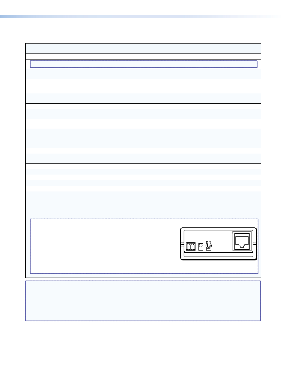
If the input cable is longer than 200 feet (60 m), place the Pre-Peak switch
on the MTP signal generator to on (up when the RJ-45 connector on the
signal generator is to the right as shown at right). If the cable is shorter
than 200 feet (60 m), place the switch down.
• The MTP signal generator does not work on cable lengths over 400 feet
(120 m). Set the level and peaking to its maximum value of 255.
Pre-Peak
is on
NOTE:
X@
= Output number
01 – (maximum number of outputs for your matrix size)
X#
= TP input number
01 – (maximum number of TP inputs for your matrix size)
X$
= Audio / RS-232 wire pair input type
0 = audio
1 = RS-232
X%
= RS-232 output insert port number
01 – 16
X^
= RS-232 output insert status or port
0 = disabled
1 = RS-232 enabled
2 = UART enabled
X&
= Input level and peaking range
000 – 255
X*
= Threshold
0 = outside of threshold
1 = within threshold
X(
= Skew adjustment range
00 – 31 (each step = 2 ns)
MTPX Plus 6400 Series Matrix Switchers • Programming Guide
73