Siemens SINUMERIK 840C User Manual
Page 954
12.93
12 Functional Descriptions
12.18.16 Examples
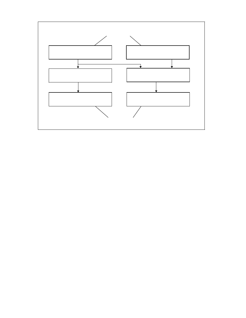
Relationship between the simulated leading axes and the following axes
Result
new Z1 value
Programmed X value
Programmed Z value
1
U= X · ––––
cos
Result
new U value
Z1= X ·(–tan
)
+Z
Real, non-cartesian
coordinate system
Simulated, cartesian
coordinate system
Example of parameterization of GI grouping machine data:
Axis
Name
1
X
(Leading drive)
2
Y
(Leading drive)
3
Z
(Leading drive)
4
Z1 (Following axis)
5
U
(Following axis)
=20.5°
GI machine data required:
•
NC MD 18444 bit0 = 1
Axis Z1 may be following axis
•
NC MD 18444 bit1 = 1
Reconfiguration permissible
•
NC MD 18444 bit2 = 1
Switchover of link factor permissible
•
NC MD 18444 bit3 = 1
Overwriting of synchronous positions permissible
•
NC MD 18445 bit0 = 1
Axis U may be following axis
•
NC MD 18445 bit1 = 1
Reconfiguration permissible
•
NC MD 18435 bit2 = 1
Switchover of link factor permissible
•
NC MD 18445 bit3 = 1
Overwriting of synchronous positions permissible
© Siemens AG 1992 All Rights Reserved 6FC5197- AA50
12–179
SINUMERIK 840C (IA)