Siemens SINUMERIK 840C User Manual
Page 241
6 NC Machine Data (NC MD), NC Setting Data (NC SD)
09.95
6.4 Axis-specific MD 1 (axial data 1)
u: Variable increment weighting pulses
364*
Default value
Lower input limit
Upper input limit
Units
1
1
65 000 (SW 1)
9999 9999 (as from SW 2)
–
Active on
Power On
v: Variable increment weighting traversing path
368*
Default value
Lower input limit
Upper input limit
Units
2
1
65 000 (SW 1)
9999 9999 (as from SW 2)
–
Active on
Power On
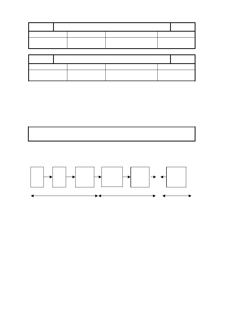
The pulses coming from the digital measuring system and the position control resolution must
be coordinated in order to produce a correctly closed position control loop.
NC machine data 364* and 368* can be used for this purpose.
The number of pulses of the encoder and the appropriate distance to go on the machine must
be known for determining machine data 364* and 368* .
The following formula represents the relation between these machine data:
Position
control
resolution
×
MD
368*
=
Measuring
system
resolution
×
MD
364*
Schematic block diagram of the position control parameters :
Comput. resoln.
Actual value adjustment
Meas. system resolution
=
Meas.
system
Mech.
gearing
Pulses
Pulse eval.
MD 364*
Pos. control
resolution
MD 1800*
Dist. to go
Pulse eval.
MD 368*
=
Multipl.
of pulses
Hardware
Note concerning upper input limits
MD 364* and MD 368* should always be reduced as much as possible (at least for values
100 000).
Note: as from SW 4
MD 3900* 3904* and 3908* in the MDD are used to automatically calculate MD 364*.
6–56
©
Siemens AG 1992 All Rights Reserved 6FC5197- AA50
SINUMERIK 840C (IA)