Siemens SINUMERIK 840C User Manual
Page 1067
12 Functional Descriptions
09.95
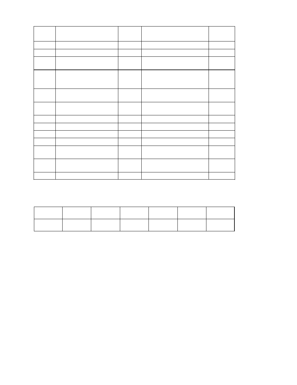
12.28.8 Overview of function identifiers and configuring parameters (DB 2, DR 2 ... DR 6)
Signal
number
Meaning
Data
format
1)
Unit
Attribute
5
Part setpoint
SL
0.01 % of max. load speed
3)
Read
6
Synchronism deviation
SL
UMS
Read
7
Angular offset (mech.
coupling)
SL
UMS
Read
8
Absolute position actual
value (without modulo
compensation)
SL
UMS
Read
9
Part actual value 1st
measuring system
SL
0.01 % of max. load speed
3)
Read
10
Part actual value 2nd
measuring system
SL
0.01 % of max. load speed
3)
Read
AXIS
100
Contour deviation
SL
UMS
Read
101
Abs. compensation value
SL
UMS
Read
SPINDLE
200
Current speed setpoint
(before ramp generator)
SL
(0.1) RPM
Read
201
Speed setpoint (ramp
generator output)
SL
(0.1) RPM
Read
202
Speed actual value
SL
(0.1) RPM
Read
Explanation of digital I/O in NCK:
Function
identifier
Explanation
Max. permissible
number
Parameter 1
Parameter 2
Parameter 3
Parameter 4
01
Digital I/O in
NCK
32
Data group
21H
Data type
Signal
number
Axis/spindle
number
The digital I/O peripherals (e.g. 6 digital inputs of Central Service Board or maximum 2 mixed
I/O modules with 2 input and output bytes each) can also be used to a limited extent in the
NCK area.
The status of these inputs/outputs can be read from the PLC by means of the high-speed data
channels. However, the outputs cannot be written from the PLC!
_______
1)
Data format
SL.. Signed Long (32 bit)
2)
Unit UMS ... Units Machine system
(0, 1) RPM ... Revolutions / minute, load-related
0.1 rpm when MD bit 520* bit 3 =1
1 rpm when MD bit 520* bit 3 = 0
3)
Load speed: 400000H corresponds to 0.01% of the max. load speed
12–292
© Siemens AG 1992 All Rights Reserved 6FC5197- AA50
SINUMERIK 840C (IA)