Siemens SINUMERIK 840C User Manual
Page 260
09.95
6 NC Machine Data (NC MD), NC Setting Data (NC SD)
6.5 Spindle-specific MD (spindle data)
Notes
•
Machine data 458* is taken into account only when a HMS servo loop module is used.
This MD also has an effect when the measuring system of the digital drive (611-D) is used.
•
The multiplication factor must be taken into account for variable increment weighting
(MD 455*, 456*).
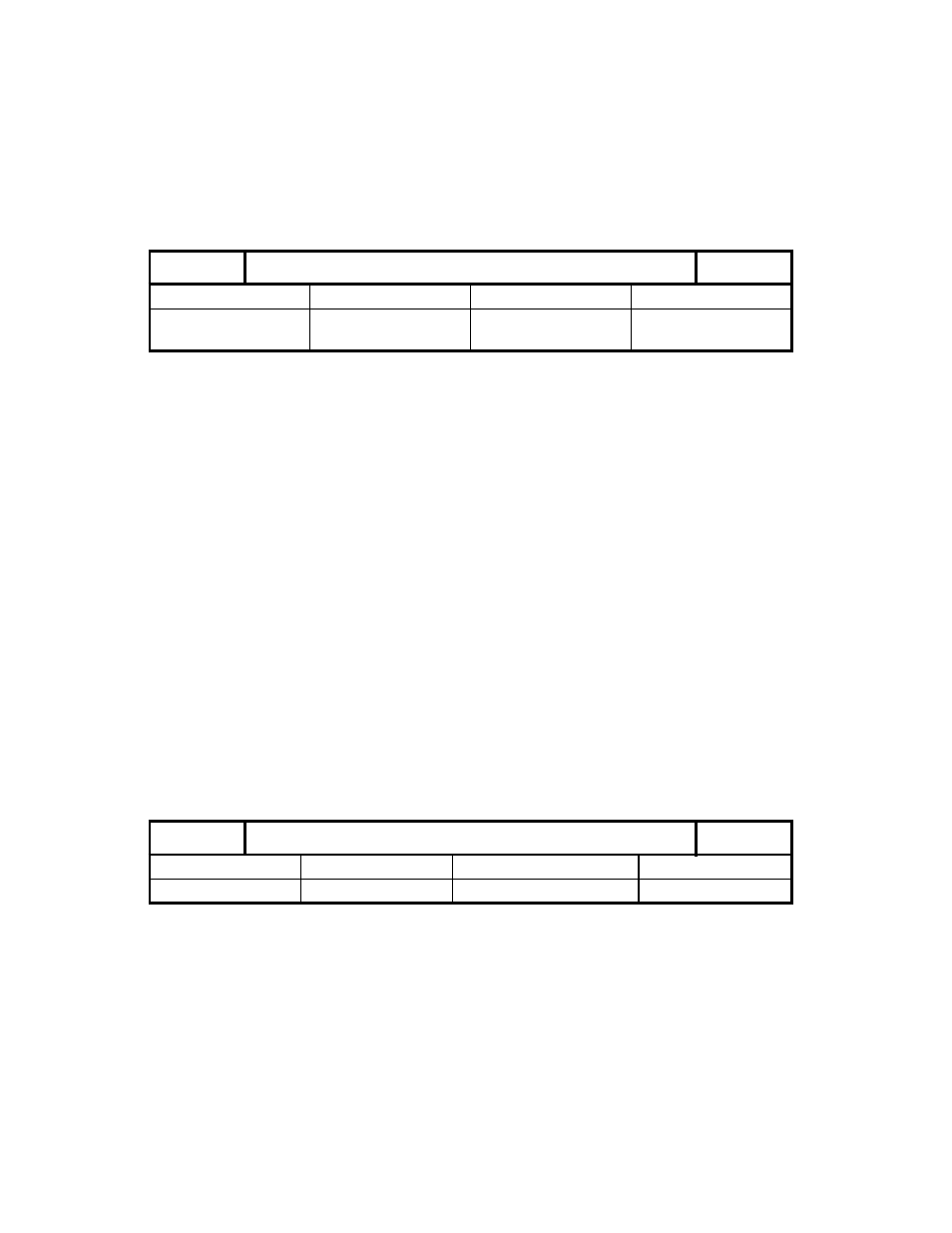
Zero mark offset
459*
Default value
Lower input limit
Upper input limit
Units
0
-99 999 999
-18 000
2)
99 999 999
18 000
2)
0.01°
Active on
Power On
Using zero mark offset, the spindle angle zero position (e.g. after M19 S0) can be made to
differ from the encoder zero mark. The spindle zero position can thus be defined arbitrarily.
In other words, the reference system for the spindle control is offset in relation to the encoder
reference system.
Note
•
Changes to MD 459* do not take effect until the spindle is resynchronized with the
encoder.
•
When specifying a positive value in MD 459*, the spindle angle zero position is offset in
the direction which corresponds to clockwise rotation (M03).
•
If a C axis is assigned to the spindle, axis MD 244* takes effect in C axis mode as soon as
the C axis has been referenced.
1)
Example
MD 4590 = 9 000
Zero mark offset by 90 degrees
M19 S270 LF
The spindle is positioned to 270° in the control reference system.
As this reference system is offset from the encoder zero mark by
90 degrees, the spindle will thus be on the encoder zero mark.
(see MD 463* for further examples)
Setpoint output (analog)
460*
Default value
Lower input limit
Upper input limit
Units
0
0
See permissible values
–
Active on
Power On
MD 460* defines the assignment of the analog setpoint speed to a servo loop module and an
output.
_______
1)
See also Section C axis mode
2)
As from SW 4
©
Siemens AG 1992 All Rights Reserved 6FC5197- AA50
6–75
SINUMERIK 840C (IA)