Siemens SINUMERIK 840C User Manual
Page 1124
08.96
12 Functional Descriptions
12.33.5 Speed setpoint filter
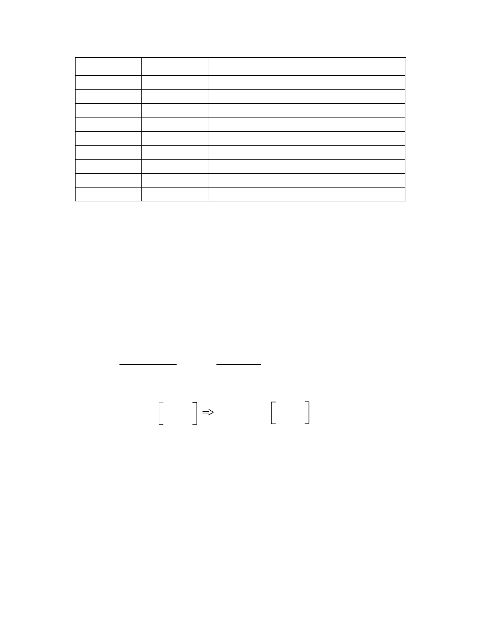
Speed setpoint filter combinations
Filter 2
Filter 1
MD 1501
PT1
PT1
300
PT1
PT2
200
PT1
BS
201
PT2
PT1
100
PT2
PT2
000
PT2
BS
001
BS
PT1
102
BS
PT2
002
BS
BS
003
12.33.5.2
Bandstops and low passes as speed setpoint filter
Bandstop
Depending on requirements, the "Bandstop" function can be set in three configurations:
•
Simple bandstop. MD 1514/MD 1517 and MD 1515/MD 1518.
•
Bandstop with adjustable damping of amplitude response plus MD 1516/MD 1519.
•
Bandstop with adjustable damping of amplitude response and increase/decrease in
amplitude response above blocking frequency plus MD 1520/MD 1519.
Note
The sampling frequency of the control (MD 1001) sets an upper limit to the blocking frequency
input (parameterization error).
1
1
MD 1514 <
=
2 x T
sampl
2 x MD 1001
MD 1001 = T
sampl
=
62.5 µs
125.0 µs
MD 1514 <
8000 Hz
4000 Hz
Low pass
In the case of rigid mechanical components, the k
v
(servo gain) factor and dynamic response
of the subordinate speed control loop (incl. filter time constants and position controller
deadtimes) are indirectly proportional for the purpose of optimizing the position control loop.
If the k
v
(servo gain) factor setting is limited to lower values due to elastic mechanical
components (table frequencies), it is possible to use the filter time constant (as a component
of the subordinate dynamic response) as an additional degree of freedom to the servo gain
factor to dampen resonance without impairing the dynamic response of the position controller.
© Siemens AG 1992 All Rights Reserved 6FC5197- AA50
12–349
SINUMERIK 840C (IA)