2 installation with adaptation characteristic – Siemens SINUMERIK 840C User Manual
Page 898
06.93
12 Functional Descriptions
12.16.3 Installation
12.16.3.2
Installation with adaptation characteristic
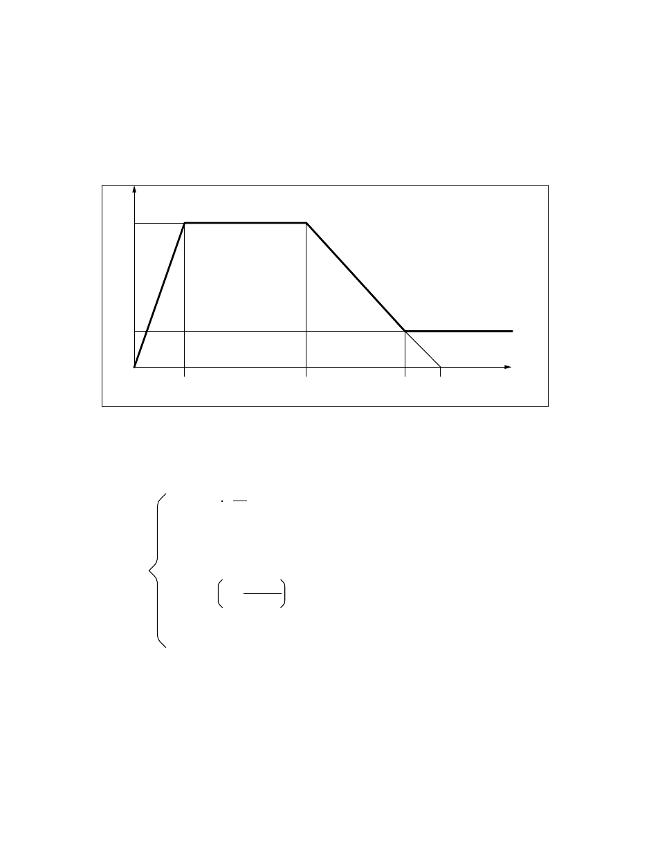
If the compensation is acceleration dependant, a characteristic must be determined in a
second stage.
The required compensation amplitudes for differend radii and velocities are determined, the
effect of the compensating amplitudes checked in a circularity test and the optimum
compensation amplitudes logged.
The following characteristic is used for the adaptation:
Figure 1
n
max
n
min
Max. amplitude MD 1232*
Minimum amplitude MD 1240*
Acceleration
MD 1244*
MD 1248*
MD 1252*
1
2
3
4
a
1
a
2
a
3
a
'3
A distinction is made between four ranges in the characteristics:
n
max
n
max
n
max
n
min
n =
for a < a
for a
1
a a
2
for a
2
< a < a
3
for a
3
a
a – a
2
a
3
– a
2
1 –
a
a
1
The characteristics in Figure 1 are used for the following examples. It is defined by the values
”Maximum compensating amplitude”, ”Minimum compensating amplitude” and the three
acceleration values a
3
, a
2
and a
1
. Considerably more measured values should be determined
as a control, most importantly there should be a sufficient number of points for high velocities
with small radii. The characteristic values are most easily derived from a graphic
representation.
© Siemens AG 1992 All Rights Reserved 6FC5197- AA50
12–123
SINUMERIK 840C (IA)