Siemens SINUMERIK 840C User Manual
Page 610
8 PLC Machine Data (PLC MD)
09.95
8.5 PLC MD for the operating system (system bits)
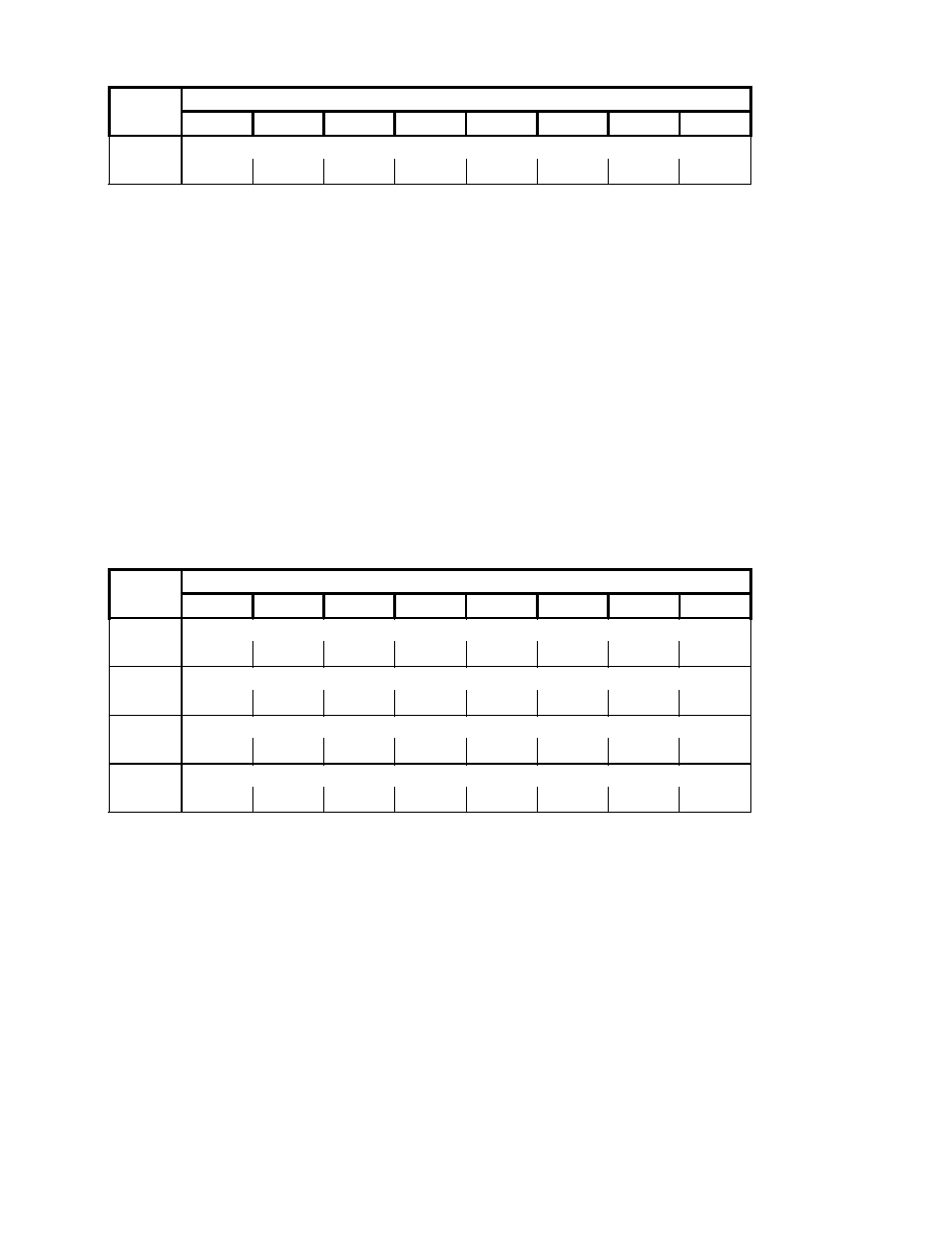
6035
DR 17
DR k+3
DL k+3
PLC MD
DB63
DW No.
Bit No.
7
6
5
4
3
2
1
0
Alarm DB 32
Default value:
All bits default to 0
K = 0, 4, 8, 12, ... 116 (1st to 30th axis)
Bit = 0
The system software does not evaluate the bits in the corresponding interface
byte for error messages.
Bit = 1
The system software evaluates the bits in the corresponding interface byte for
error messages.
Notes:
1) The bit applies to all axes.
2) If the identical bit is also set for operational messages (PLC MD 6043), the PLC goes into
the Stop loop.
Sample application:
DB 32 D 3.3
1 signal error message 8211;
PLC MD 6035.1=
1
See PLC Installation Section.
6036
DL 18
DR 4
DL 4
DR 3
DL 3
DR 2
DL 2
DR 1
DL 1
6037
DR 18
DR 8
DL 8
DR 7
DL 7
DR 6
DL 6
DR 5
DL 5
6038
DL 19
DR 12
DL 12
DR 11
DL 11
DR 10
DL 10
DR 9
DL 9
6039
DR 19
DL 16
DR 15
DL 15
DR 14
DL 14
DR 13
DL 13
PLC MD
DB63
DW No.
Bit No.
7
6
5
4
3
2
1
0
Alarm DB 58
Alarm DB 58
Alarm DB 58
Alarm DB 58
Default value:
All bits default to 0
Bit = 0
The system software does not evaluate the bits in the corresponding interface
byte for error messages.
Bit = 1
The system software evaluates the bits in the corresponding interface byte for
error messages.
Note:
If the identical bit is also set for operational messages (PLC MD 6044-6047), the PLC goes
into the Stop loop.
Sample application:
DB 58 D 3.10
1 signal error message 9034;
PLC MD 6039.4 =
1
8–18
© Siemens AG 1992 All Rights Reserved 6FC5197- AA50
SINUMERIK 840C (IA)