10 axis and spindle installation – Siemens SINUMERIK 840C User Manual
Page 691
09.95
10 Axis and Spindle Installation
10.1 Determining sampling interval and interpolation time
10
Axis and Spindle Installation
10.1
Determining sampling interval and interpolation time
Corresponding data
MD 155
NC MD Position controller basic clock frequency
MD 160
Ratio of interpolation to position control
MD 168
Drive basic cycle time
MD 1396*/MD 466*
Position control clock frequency increase axis/spindle
Functional description
MD 155 and MD 168 are used to set the position control basic clock frequency, and MD 160
to set the ratio of the interpolation time to the sampling interval. The objective is to keep both
these times to a minimum.
In order to off-load the CPU as much as possible, axes that are not used for workpiece
machining (auxiliary axes, loader axes) can be controlled at longer intervals. MD 1396* is used
to increase the sampling interval.
The sampling interval is the interval at which the control forwards a new setpoint to the axes
and computes the actual value.
MD466* is valid for the spindle rather than MD1396*.
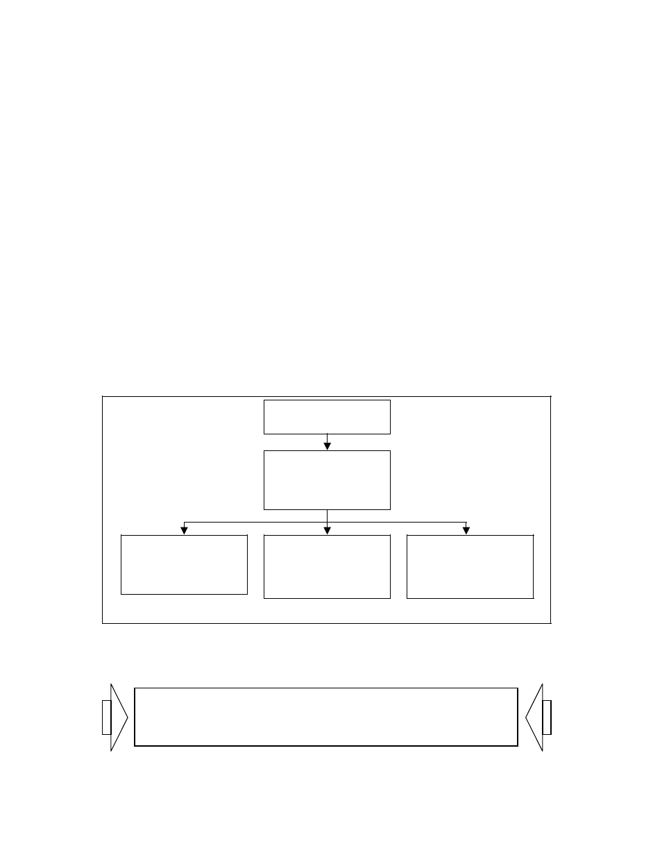
Determination of sampling interval and interpolation time
MD 168
X
MD 155
=Position control basic
clock frequency
X
MD 160
=IPO clock frequency
Drive basic cycle time
[62.5
µs
]
Spindles
Axes
X
MD 1396*
=Position control clock
frequency
X
MD 466*
=Position control clock
frequency
From software version 3 onwards, the machine data dialog
handels the standard start-up.
See Section entitled Machine Data Dialog (MDD).
© Siemens AG 1992 All Rights Reserved 6FC5197- AA50
10–1
SINUMERIK 840C (IA)